I started this blog assuming anyone reading it would know all about the Arduino, and be ready to follow me right away. Then I started reading about aircraft homebuilders building relay trays, and all kinds of PLC and silly other things, and it occurred to me, not everyone knows about micro-controllers and the simplicity they can provide.
The Arduino is a series of micro-controllers that are organized in a simple consistent design. There are some that are smaller than the normal design, but most of the popular boards support the basic pinout. The most popular boards are the UNO, and the Mega. All the boards are programmed the same way using the Arduino Integrated Development Environment (IDE) over a USB connection.
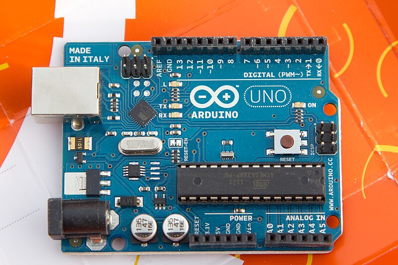
The smaller boards like the Uno have about 16 general purpose IO pins, 6 Analog input pins, a serial port (SPI), and various power pins. The organization of these pins is consistent for most boards. The Uno, Diecimila, Duemilanove and the Leanardo are basically the same.
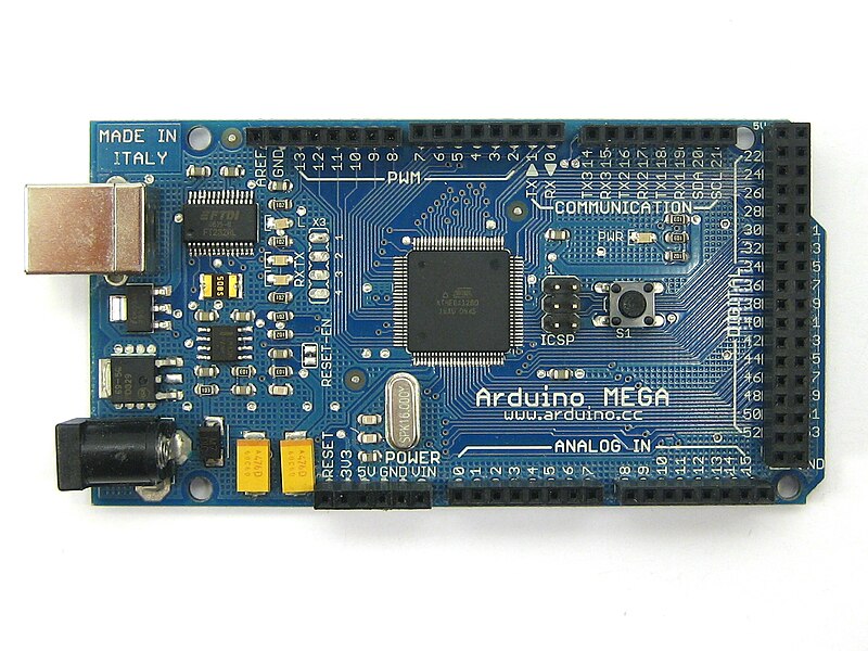
The larger boards like the Mega, have over 50 IO pins, 16 Analog input pins, the same serial interface (SPI) and power pins as the smaller boards. The layout of the board starts with the same pin organization as the smaller boards, but since the Mega board is longer the extra pins are out past the edge of the smaller boards.
Relying on this consistent pin layout has allowed expansion boards to be built. These expansion boards are known as "shields". Most of the shields add specific functionality to the basic Arduino. Shields include servo and motor controllers, GPS, ethernet, WiFi, and Bluetooth. I think there are over 100 different shields for the Arduino family of controllers as of now.
Many of the shields allow other shields to plug into them. Having a whole stack of shields isn't uncommon. A project may include an Arduino processor board as the base, a special IO shield in the middle and either a bluetooth or WiFi shield plugged into that. The only limit to the number of shields is power available, and mechanical constraints.
Using an Arduino can be done with only the board and a USB cable. All the programming will be done using the USB cable, and power on the USB can supply the board. Most computers are limited on the amount of power supplied over the USB port, so there is a second coax power connector available to power the Arduino with more if needed for the various shields. The Arduino can run off a phone charger USB adapter once a program is loaded.
Many retail outlets are selling the Arduino processor boards and shields. Radio Shack, Micro Center and Fry's all have Arduino boards in most of their stores. Many online electronic suppliers also have Arduino boards and shields, and their selection can be more extensive. The UNO boards can be bought for as little as $10 retail. Buying a starter kit is a good idea if you have never worked extensively with electronics, since this will come with wires, LED lights, switches and various other components making connecting an Arduino to an airplane easier. Shop around, see what you like.
The Arduino IDE is available from the Arduino web site for free. There is a version of the IDE available for most computers including: Windows, Mac, and Linux. It is an open source project, if you have another platform, you may need to get the source and compile it for your platform.
Installing the IDE is occasionally a challenge on Windows. The FTDI USB driver isn't included with Windows, so you may need to download the driver for your OS. Mac and Linux usually work without any challenges. There is plenty of help installing using the Arduino.cc forums. If you see an error, just enter that error message in the search bar for the forums, and it will probably take you to the solution.
Programming an Arduino is very simple. The IDE comes with many examples, that will run on most boards. The programs written for the Arduino in the IDE are called "sketches". The simplest example sketch is a blinking light. The blinking light sketch will blink the light on the Arduino board itself.

The sketches included are source code. To select the blink sketch, open the IDE and select File->Examples->Basics->Blink. A new window should open, showing the source code for the blink example. The text between "/*" and "*/" are comments, as is the text after "//". If you have ever worked with C or Java this syntax should be very familiar. Comments are only there for the people reading the code, the computer doesn't use that information at all.
/*
  Blink
  Turns on an LED on for one second, then off for one second, repeatedly.

  This example code is in the public domain.
 */

// Pin 13 has an LED connected on most Arduino boards.
// give it a name:
int led = 13;

// the setup routine runs once when you press reset:
void setup() {
  // initialize the digital pin as an output.
  pinMode(led, OUTPUT);
}

// the loop routine runs over and over again forever:
void loop() {
  digitalWrite(led, HIGH);   // turn the LED on (HIGH is the voltage level)
  delay(1000);               // wait for a second
  digitalWrite(led, LOW);    // turn the LED off by making the voltage LOW
  delay(1000);               // wait for a second
}
There are two kinds of syntax after the inital comments, function definitions and variable declarations. The line:
int led = 13;
is a variable declaration, saying some name "led" is declared as 13, at least for now. It is at the top of the program making it a global variable. Global variables can be used anywhere in the program. In this case, when the word "led" shows up, the value 13 will replace it.
The two lines:
void setup()
void loop()
are function definitions. Arduino will call these two functions in every program. The setup() function is used at the begining of a program to make sure the board is set the way you want. The loop function is called the rest of the program run time, and does all the real work.
For the blink program, the setup() function is used to set the IO pin "led" (13) to be output using the pinMode() function call. Output means the computer will send messages to that pin. Input would be used for reading messages from that pin.
For the blink program, the loop() function is what does the actual blinking. digitalWrite() is a function that is part of the standard library, allowing data to be set on specific output pins. The first thing done is to digital write to the "led" (13) pin to be high, or to send 5V on that pin. delay() another function in the standard library that tells the computer to wait here for some milliseconds, in this case 1000 milliseconds, or one second. The next digital write will set the "led" (13) pin to be 0 volts or off and then the computer will delay another second and exit the loop function. The built in Arduino manager will call the loop function as soon as this loop function finishes. Each of the lines has a "//" followed by an explaination comment as to what that line does, and it helps the people reading the source code, but is only optional.
To send this program to your Arduino, the IDE will need to be set up. Under Tools select Board and the board you are trying to program. If you have an Uno, select Tools->Board->Arduino UNO from the boards menu. Then you need to set the port. The port will be the place the board is connected to as your computer sees it. For Windows it may be COM6 or something other than COM1 or COM2. For Linux, it will probably be /dev/ttyUSB2 or something, use dmesg to see what the computer named the port when the board was plugged in. The Adruino web site has all the information in the getting started page.
Once the board and the port are set, the sketch can be uploaded to the board. Press the forward arrow button or File->Upload or ctrl+U, to upload the code to the Arduino. At the bottom of the IDE window, the current status will be displayed. First the source code will need to be converted to AVR binary code through the process of compilation, then the resulting binary code will be sent through the serial port to the Arduino board, and the process will start running.
If everything has gone well, the LED light on the board will start blinking one second on, one second off. The code is "burned" in to the computers memory. When the Arduino is unplugged, the code is still there, but the processor will stop running. Plugging the Arduino back in, the blinking will start automatically.
To change the pattern of the blink, in the IDE, change some of the values. To make the light appear to flash, change the delay() value after the on digitalWrite() call. A very quick on, could be something like a tenth of a second (100ms). Delete one of the zeros, and upload your code. Notice how the light just blinks briefly, and stays off for the full second still. Other settings can be used to give other patterns.
I am going to end this article now. I think there is a lot to chew on, and hopefully I have wet your appetite to try new things related to controlling things using a microcontroller. Next time I will add inputs and additional outputs, including motors, switches and lights.
What else do you want to know?
No comments:
Post a Comment