Sunday, July 27, 2014

Arduino For Pilots

I am a technology geek. If it has a computer, I at least look at it, and maybe buy one to play with. The Arduino first became available almost 10 years ago as a simple way for hobbyists to get started with microcontrollers. I started playing with AVR micro-controllers, probably 10 years ago, because they were already simple. The Arduino platform makes it easy to do things with quickly.

I started this blog assuming anyone reading it would know all about the Arduino, and be ready to follow me right away. Then I started reading about aircraft homebuilders building relay trays, and all kinds of PLC and silly other things, and it occurred to me, not everyone knows about micro-controllers and the simplicity they can provide.

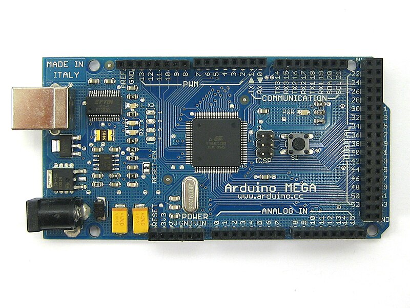
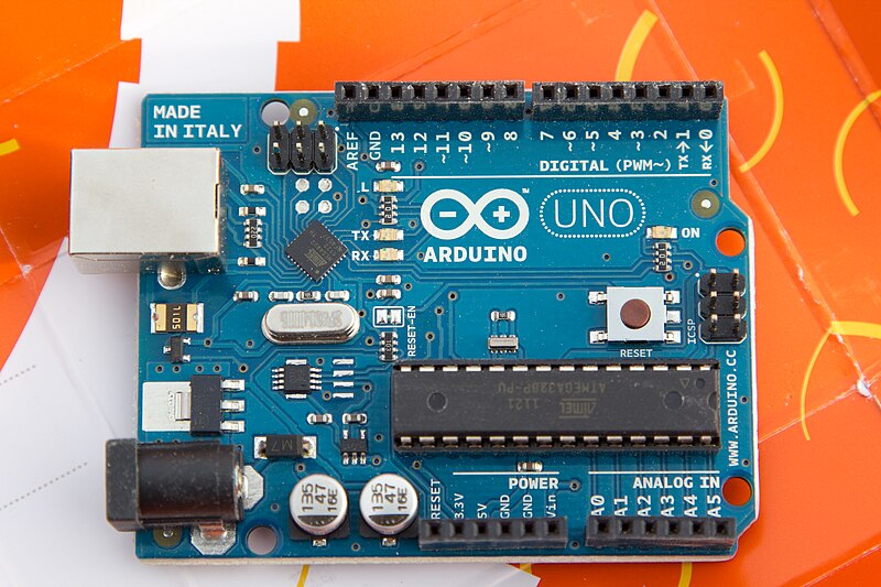
The Arduino is a series of micro-controllers that are organized in a simple consistent design. There are some that are smaller than the normal design, but most of the popular boards support the basic pinout. The most popular boards are the UNO, and the Mega. All the boards are programmed the same way using the Arduino Integrated Development Environment (IDE) over a USB connection.


The smaller boards like the Uno have about 16 general purpose IO pins, 6 Analog input pins, a serial port (SPI), and various power pins. The organization of these pins is consistent for most boards. The Uno, Diecimila, Duemilanove and the Leanardo are basically the same.


The larger boards like the Mega, have over 50 IO pins, 16 Analog input pins, the same serial interface (SPI) and power pins as the smaller boards. The layout of the board starts with the same pin organization as the smaller boards, but since the Mega board is longer the extra pins are out past the edge of the smaller boards.

Relying on this consistent pin layout has allowed expansion boards to be built. These expansion boards are known as "shields". Most of the shields add specific functionality to the basic Arduino. Shields include servo and motor controllers, GPS, ethernet, WiFi, and Bluetooth. I think there are over 100 different shields for the Arduino family of controllers as of now. 

Many of the shields allow other shields to plug into them. Having a whole stack of shields isn't uncommon. A project may include an Arduino processor board as the base, a special IO shield in the middle and either a bluetooth or WiFi shield plugged into that. The only limit to the number of shields is power available, and mechanical constraints.

Using an Arduino can be done with only the board and a USB cable. All the programming will be done using the USB cable, and power on the USB can supply the board. Most computers are limited on the amount of power supplied over the USB port, so there is a second coax power connector available to power the Arduino with more if needed for the various shields. The Arduino can run off a phone charger USB adapter once a program is loaded.

Many retail outlets are selling the Arduino processor boards and shields. Radio Shack, Micro Center and Fry's all have Arduino boards in most of their stores. Many online electronic suppliers also have Arduino boards and shields, and their selection can be more extensive. The UNO boards can be bought for as little as $10 retail. Buying a starter kit is a good idea if you have never worked extensively with electronics, since this will come with wires, LED lights, switches and various other components making connecting an Arduino to an airplane easier.  Shop around, see what you like.

The Arduino IDE is available from the Arduino web site for free. There is a version of the IDE available for most computers including: Windows, Mac, and Linux. It is an open source project, if you have another platform, you may need to get the source and compile it for your platform.

Installing the IDE is occasionally a challenge on Windows. The FTDI USB driver isn't included with Windows, so you may need to download the driver for your OS. Mac and Linux usually work without any challenges. There is plenty of help installing using the Arduino.cc forums. If you see an error, just enter that error message in the search bar for the forums, and it will probably take you to the solution.

Programming an Arduino is very simple. The IDE comes with many examples, that will run on most boards. The programs written for the Arduino in the IDE are called "sketches". The simplest example sketch is a blinking light. The blinking light sketch will blink the light on the Arduino board itself.


The sketches included are source code. To select the blink sketch, open the IDE and select File->Examples->Basics->Blink. A new window should open, showing the source code for the blink example. The text between "/*" and "*/" are comments, as is the text after "//". If you have ever worked with C or Java this syntax should be very familiar. Comments are only there for the people reading the code, the computer doesn't use that information at all.

/*
  Blink
  Turns on an LED on for one second, then off for one second, repeatedly.
 
  This example code is in the public domain.
 */
 
// Pin 13 has an LED connected on most Arduino boards.
// give it a name:
int led = 13;

// the setup routine runs once when you press reset:
void setup() {                
  // initialize the digital pin as an output.
  pinMode(led, OUTPUT);     
}

// the loop routine runs over and over again forever:
void loop() {
  digitalWrite(led, HIGH);   // turn the LED on (HIGH is the voltage level)
  delay(1000);               // wait for a second
  digitalWrite(led, LOW);    // turn the LED off by making the voltage LOW
  delay(1000);               // wait for a second
}


There are two kinds of syntax after the inital comments, function definitions and variable declarations. The line:

   int led = 13;

is a variable declaration, saying some name "led" is declared as 13, at least for now. It is at the top of the program making it a global variable. Global variables can be used anywhere in the program. In this case, when the word "led" shows up, the value 13 will replace it.

The two lines:
  void setup()
  void loop()


are function definitions. Arduino will call these two functions in every program. The setup() function is used at the begining of a program to make sure the board is set the way you want. The loop function is called the rest of the program run time, and does all the real work.

For the blink program, the setup() function is used to set the IO pin "led" (13) to be output using the pinMode() function call. Output means the computer will send messages to that pin. Input would be used for reading messages from that pin.

For the blink program, the loop() function is what does the actual blinking. digitalWrite() is a function that is part of the standard library, allowing data to be set on specific output pins. The first thing done is to digital write to the "led" (13) pin to be high, or to send 5V on that pin. delay() another function in the standard library that tells the computer to wait here for some milliseconds, in this case 1000 milliseconds, or one second. The next digital write will set the "led" (13) pin to be 0 volts or off and then the computer will delay another second and exit the loop function. The built in Arduino manager will call the loop function as soon as this loop function finishes. Each of the lines has a "//" followed by an explaination comment as to what that line does, and it helps the people reading the source code, but is only optional.

To send this program to your Arduino, the IDE will need to be set up.  Under Tools select Board and the board you are trying to program. If you have an Uno, select Tools->Board->Arduino UNO from the boards menu. Then you need to set the port. The port will be the place the board is connected to as your computer sees it. For Windows it may be COM6 or something other than COM1 or COM2. For Linux, it will probably be /dev/ttyUSB2 or something, use dmesg to see what the computer named the port when the board was plugged in. The Adruino web site has all the information in the getting started page.

Once the board and the port are set, the sketch can be uploaded to the board.  Press the forward arrow button or File->Upload or ctrl+U, to upload the code to the Arduino. At the bottom of the IDE window, the current status will be displayed. First the source code will need to be converted to AVR binary code through the process of compilation, then the resulting binary code will be sent through the serial port to the Arduino board, and the process will start running.

If everything has gone well, the LED light on the board will start blinking one second on, one second off. The code is "burned" in to the computers memory. When the Arduino is unplugged, the code is still there, but the processor will stop running. Plugging the Arduino back in, the blinking will start automatically.

To change the pattern of the blink, in the IDE, change some of the values. To make the light appear to flash, change the delay() value after the on digitalWrite() call. A very quick on, could be something like a tenth of a second (100ms). Delete one of the zeros, and upload your code. Notice how the light just blinks briefly, and stays off for the full second still. Other settings can be used to give other patterns.

I am going to end this article now. I think there is a lot to chew on, and hopefully I have wet your appetite to try new things related to controlling things using a microcontroller. Next time I will add inputs and additional outputs, including motors, switches and lights.

What else do you want to know?

Friday, June 27, 2014

Data Comm Tools We Need

I spent the last week on a business trip, and managed to go most of the week without WiFi. The airplane I flew on didn't have WiFi, and while in the car I didn't have it either. I was staying at a 5 star hotel for 4 nights, and had only marginal coverage, at $13 a night. I ended up using my mobile hot spot on my phone and burned through over half my monthly allotment LTE internet in 4 days. I learned how much I rely on data connections.


Several years ago, probably 1998 or so, my wife and I were at Oshkosh, and walked by the Iridium booth. The Iridium sales person offered us a free phone call to see how great their products are, and maybe we could use them in our airplane. This was before my wife or I had a cell phone, and we wanted to check in on the kids. After three or 4 failures, we never got to talk to the kids, and we walked away unimpressed.

About a week ago, the Airplane Geeks had the president of Iridium on the show and allowed him to hawk his products.He presented a new product that sounds like something pilots can use in the plane, and maybe other times as well. The Iridium Go looks to be the perfect implementation of the Iridium network for us.

The Iridium Go is a WiFi hotspot that will work anywhere in the world, at almost any altitude. This is the opportunity to make a tablet and phone work anywhere all the time. When in the air, the tablet can get all the data updates desired, along with making VOIP phone calls on the phone. The Go also has tracking and other useful features built in.

I know FIS-B and TIS-B should have much of the datalink covered, there are some things it won't have covered. Items like downloading whole graphical charts while in the air, or additional weather information will not be available over FIS-B.  TIS-B and FIS-B aren't available outside the CONUS either, operations there will benefit from additional datalinks.

Airlines have the ability to use Iridium datalink today, and the ICAO flight plan has a capability letter reserved for CPDLC using Iridium (J7 CPDLC FANS 1/A SATCOM (Iridium)) in Item 10. To put Iridium radios in commercial aircraft is a very expensive aftermarket event. Using the Iridium Go for non-safety of flight purposes is a much smaller cost (More than an order of magnitude!).

The price is around $600 for the GO, and while that sounds high, consider the cost of a typical smart phone is in a similar ballpark (off contract). One might guess if these devices become quite popular, the price may come down.

For tooling around in your Taylorcraft, this might be overkill, but I could see it becoming almost an expected item on a Citation, or King Air. People rely on data communications a bit more in the 21st century.

(Iridium hasn't talked to me at all, I saw this and thought this is  great product!)


Friday, June 6, 2014

Stuff To Learn

I knew the different Arduino boards are all a little different, but I didn't realize the Arduino Mega 256 was really different. My other Arduino Mega is only a 128. The Mega 128 and most of the other Arduino boards use the FTDI USB interface. The Mega 256 uses a ATMega8U2 chip, like the UNO. The boards sure look the same


Now I am using Linux to do development, so the serial port ends up being called /dev/ttyACM0 instead of some /dev/ttyUSB0. No big deal really, it is just I was surprised there were more differences than I expected. The Arduino on Linux page has many helps to get things working.

I took the basic sketch, blink and modified the loop to be sure I knew it was my code running on it.

// the loop routine runs over and over again forever:
void loop() {
  digitalWrite(led, HIGH);   // turn the LED on (HIGH is the voltage level)
  delay(100);               // wait for a tenth of a second
  digitalWrite(led, LOW);    // turn the LED off by making the voltage LOW
  delay(100);               // wait for a tenth of a second
  digitalWrite(led, HIGH);   // turn the LED on (HIGH is the voltage level)
  delay(100);               // wait for a tenth of a second
  digitalWrite(led, LOW);    // turn the LED off by making the voltage LOW
  delay(100);               // wait for a tenth of a second
  
  digitalWrite(led, HIGH);   // turn the LED on (HIGH is the voltage level)
  delay(1000);               // wait for a second
  digitalWrite(led, LOW);    // turn the LED off by making the voltage LOW
  delay(1000);               // wait for a second
}


Now I want to get things working with the display. I bought a LCD touch screen for this. The screen looks familiar, almost identical to the Sharp Zaurus screen. (we can talk all we want about iPhone/Android but the reality was there were smart devices running a *nix flavor waiting for a phone a long time before either were invented! Zaurus was the first one I had, the Nokia 770 was the second, wifi enabled internet connected personal mobile devices).


There is a thread on the Arduino forums about this device, including locations of the libraries. I am going to build a minimal graphics library so I can build a display of the basics before I start using the bluetooth connection to the Android. 


Monday, May 19, 2014

Doing The Annual Inspection

The weather is getting nice, and I am wanting to work on the plane again. It should be put in condition to fly, and that requires an annual condition inspection. My airplane, being an experimental, and built by me mostly, I have the ability to do my own conditional inspection and sign it off. It hasn't flown for almost 3 years, so I haven't done a complete conditional inspection for some of those years. This one is going to be thorough, I am in no hurry to actually fly.


I've got everything opened up. There are items that need repair (IE drip rail in the front that I broke while storing a box inside the plane), and other things that need a good looking at. I am changing the oil, and sent a sample off to a lab for analysis, to be sure the last couple years of dis-use hasn't done significant damage to the engine. The lab will test the oil for elevated levels of metals that may be early signs of engine damage.


I am looking at the firewall extensively for the engine monitor, and where to attach the monitoring computer.  Most of the smaller wires between the engine and the firewall are for sensors. The wires around the oil filter are oil temperature and pressure sensors. The silvery wires are EGT/CHT thermocouple wires. Under the engine are the fuel pressure wires.  There are the ammeter wires on either side of the shunt (that is a bit of old fashioned technology).

In the annual inspection, I found the ammeter light is burned out. This light is only needed for night flying, since I can see the instruments during the day. Each engine instrument has it's own light bulb, so I am 1/6th of the way through needing to replace them all. It'll be good to replace all the engine instruments with a smart box to monitor all this, as well as display current state.

I've started on the bluetooth code. That is a bigger challenge than I thought, mostly because the Android emulator doesn't support bluetooth. I need to keep my phone plugged in and use that for the tester. It isn't bad, but the phone has lots going on, so the log files scroll fast (and this is my only phone right now.

Soon the annual will be done, and hopefully about that time, I'll be ready to put my arduino in the plane, and start testing some of this. In the mean time, I've ordered another arduino, a mega 256. It seemed I ordered that the same day the arduino zero came out. Why am I messing with 8 bit micros when 32 bitters are about the same price? I don't know, comfort maybe, or maybe it is all I need, the 32bits may not get me anything. (The zero only has the same number of IO pins as an uno, so there isn't a big win yet, some day there may be a mega zero, until then, I'll keep using the mega).

Tuesday, May 13, 2014

More Engine Monitor Updates

This will be kind of a quick post, but the gist of it is, I've been busy. In between getting a new version of my other app out, and explaining the technology behind these gauges on my other blog, I haven't been watching a lot of TV or hanging out in bars.

The new gauges have options that work, and the interface and abstract implementation make these very flexible. Looking at all the gauges, they mostly have the same call, the size differences are sort of hard coded.

In the picture above, you will see round and bar gauges, mostly the same as before. The new changes are the round gauges can go in either direction, be 270 degree, or 180 degree (any sweep angle should work) There is one CircleGauge class that actually draws them all! The CircleGauge class is extended by things like the Ammeter class, or the Volts Meter class.

The gauges have options for clockwise/counter-clockwise, ticks, and various color options (I haven't been setting the color options, these are the  default values. The gauges can have a rotated start angle, and display the title and value in the center of the gauge.

The gauges all get their values from an EngineValues class, that can be set at any time. The next steps will be to put in the bluetooth reading code that will allow me to connect the Arduino to the engine and start measuring values.

What-cha think? Am I heading in the right direction?

Saturday, April 12, 2014

Engine Monitor Progress

I am gaining a bit of experience in Android development. Some things I did in that last app are helping, while I need to learn more to make this work. One thing I have clearly learned, the drawing canvas can be made into tiles. This is important, since if the app is to display both in portrait and landscape, it will be much easier to move individual gauges around than trying to use different offsets depending on orientation.

rough example


The other thing I learned, these gauges can have a million options! I may need about half that many before I am done as well. Should the round gauge turn clock wise or counter clock wise? Should the green arc be thick or thin, should the ticks be shown or not. Of course I can add all those options, and I still need to add more.

I've built the individual instruments using normal Object Oriented (OO) concepts. I could just as easily substituted the tachometer as a bar graph as a round gauge. I also have the ability to build an new type that can be a line graph or something, and only have to change the code a little. I can change the individual gauges, and probably not have to change the implementers code as well.

The OO concept allows a great deal of flexibility. Everything is abstracted away, such that the value of the fuel pressure will not really care what color the pointer is, or that the gauge is round or some other shape. Where it is placed on the screen is equally irrelevant, and allows the user to change the layout of the screen to suit their needs, and present the most important information in the most prominent position.

I am making progress, I just keep getting bogged down in implementation details, that can probably wait. Some of you are looking at this and saying, "it isn't very good". Fine, tell me what other things I should change to make it better looking. I've already considered OpenGL 3D looking instruments, and non-linear scales, red lines at limits, and many other things. The app will include audio and visual alerts depending on settings.

For now, I have all the instruments I need for my airplane on the screen. I have provisions in the code for 6 and 8 cylinder EGT/CHT values, as well as manifold pressure, and temperature. I want the screen layout to be customizable by the user, so they can pick the instruments they want, and where they are on the display.  


 Thanks for your feedback so far.


Sunday, April 6, 2014

After You Rewire it...

Yesterday I stopped by an estate sale. They had a Robosapian V2 for $10. This is a robot I've wanted for years, but they cost more than I could justify. I thought $10, why not. The remote seemed to work, and it had batteries in it, I thought for $10, I would take a chance on it.


It needs 6D cells and 4AAA batteries, so I stopped off and picked up some batteries for another $15. So now I am $25 into it, and it doesn't seem to work. My normal mode after buying something like this, and finding it doesn't work, is I Google for similiar failure modes. This failure mode is, it does nothing. I opened up the feet again to be sure I put the batteries in the right way, which I have, but the one pair of AAA batteries are super hot, like I can't hold them.

Reading some of the fixes suggested, was a youtube video about how easy it is to rewire this thing. I watched about half of it, and thought, this is like Tim Taylor rewiring everything just because. Another site suggested rewiring the legs. The one site suggested it is easy to open the robot up, so I thought, I can open up the torso to measure voltages on the main board.

Insulation has flaked off and is covering bits of the robot insides. 


What greeted me when I opened it up was shocking! Insulation just flaking off of the wires. Most of the wires that went to the legs had about 50% of the insulation missing. I continued opening up the robot, and when I got to the legs, there were parts where all I saw was a mass of copper, you could no longer tell one wire from another.

I thought I would try the rewiring repair. I went to Radio Shack to see what they had for wire. There was a significant gap between the 22GA wire and the 30GA wirewrap wire that they didn't have. I bought the 22GA wire to use for the motor power, and decided to cannibalize a Cat 5 cable for the logic wiring. It took about 4 hours to do all the wiring. There are several sites with details on what the wires are for.

I want to blame some MBA or manager for making a really bad choice here. I don't know for sure, but someone at the company decided to cut some corners with the quality of the wire. Some of the wire in the robot is fine, but the critical wires (the ones going from the body where the computer is, to the feet where the batteries are, and they move a lot) are just crap.

I was short of resources as well. The connectors that are in the robot are pretty cheap as well, but are a common connector. They have tin crimp on pins. Rather than risk the whole pin, or the body of the connector, I decided to strip back about an 1/8" of wire and solder my new wire on with some heat shrink to insulate the connection.

Once I got the wiring done, it still didn't work. I tried using a meter to trace the trouble. I was not getting any voltage from the AAA batteries in the one foot. When I opened that up, I found the connector in the cover was covered with corrosion, and not making good contact. After cleaning up the connection here, the robot started jiggling around and talking!


Success! I now had a working Robosapian V2. I started putting the panels back on, and covering the robot up, so it looked like it did when I brought it home. I messed up on some of the screw placement, but it went together, and looked good.

I played with the sensors for a little while last night. The blob detector is pretty good, and worked really well. The motion detector was pretty good at well, I could get it to flail backwards and scream when I swatted my hand towards the head. It walked and reached with the remote. So I went to bed.

When I got up this morning, I started messing with it more. I wasn't using the manual, just randomly pushing buttons. I clicked on the "D" button that starts the dance routine. It was playing music and moving quite a lot, then it quit. It seemed to quit on a proper down beat, but was in an odd position to end a dance.

3 of 6 wires are broken from white connector


Nothing worked again. Grrr! how much do I need to open up to find the trouble this time?  I opened the torso, and the trouble was obvious. My soldering on to the connector ends made the wire brittle. People have told me before, "don't solder your crimp connectors, it makes the wire brittle", but in this case, I didn't have much choice. Most of the wire was already missing the insulation, and I didn't think making long pigtails with lots of heat shrink was a good idea. (I didn't think of long heat shrink coated wires at all).

I've ordered some new connectors. I will replace all 4 of the connectors I soldered to like that, and make sure there is enough jiggle room between the connector and the solder joint.

After you rewire it, you do some pretty cool things with this robot!

These robots are a challenge.