Saturday, February 14, 2015

ADS-B in and out for under $1000

The FAA made a reasonable choice. Well, it was forced upon them, because of their own rules. The ADS-B specs were written such that certified ADS-B solutions must be installed using a supplemental type certificate (STC) process. There are some aircraft that aren't "type certificated", including experimental aircraft, that could be supplemented. The FAA has changed the rules to allow aircraft without type certificates to have avionics installed that are not certified to the technical standards order (TSO). Most nav/com radios in GA aircraft do not have TSO'd radios, but the FAA wrote the ADS-B rule to mandate TSO'd ADS-B equipment. TSO'd equipment is required on aircraft used for commercial operations.

To obtain the TSO, requires certification from the FAA. As things are, there are tests to be taken and paperwork to file, and the process takes time, and money to complete. That money ends up raising the price of the equipment beyond the bill of material (BOM) costs. In the end, you and I pay for this certification. The ADS-B equipment manufacturers were including this in the price we paid for the UAT or transponder.


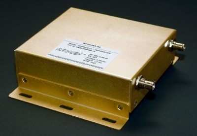
Now without the need for the TSO certification, the equipment manufacturers should be able to sell equipment for a little less. One manufacturer, so far, has taken this to an extreme. NavWorx will sell a UAT for $699 for a limited time for experimental aircraft. This device is ADS-B UAT in and out, with built in GPS.   The data can be connected RS-232, Bluetooth or WiFi to a display including mode manufacturers MFDs and Tablets.

It will need a couple antennas, one for the UAT and the other for the GPS. There will need some "baro" aiding, to allow accurate altitude reporting. The baro input can come from the transponder encoder if it includes RS-232 output, or can come from a specific NavWorx TransMonSPE device for another $169.

Hopefully this is the start of the flood, but in the mean time, this is certainly welcome news. I knew it was possible, and hopefully NavWorx will keep going offering even better devices, at reasonable prices.

You gonna buy one? I am pretty sure I will.


Saturday, January 10, 2015

Another SDR, and this one is interesting...

What have I been saying, ADS/B in and out for under $1000 is possible. There is a guy with an SDR transceiver that will work everywhere 100MHz to 1000Mhz! The Whitebox SDR is being developed and has a smaller following. This SDR has it's own processor on it and can do all the modulation/demodulation on board. The bill of materials for the board is about $300, making retail under $1000 quite possible.

The name is Whitebox as opposed to blackbox because everything about it is known. The more you know the more you can do with it! The source code, schematics and board layouts are on github. Unless you have looked into SDR programming, there may not be much useful there. If you have looked at gnu radio or any of the RTL-SDR programs, this should look quite similar.

The project hasn't changed status in a little over a year, although the author has done several recent interviews on some ham radio podcasts. There was quite a bit of discussion around the 2013 Dayton Hamvention. I believe this device is pretty solid, but I don't have one yet.

Remember that UAT frequency is 978MHz, toward the top end of the limit if this device. It should be no trouble to write the code for a UAT device. The USB out from this board could easily be connected to an external computer, including a tablet.

It will take some software development to finish this project, but with a little bit of work, suddenly there would be a UAT available for under $1000.

Flying Magazine recently published an article about a portable ADS/B in/out device that is under $1500. It may not be under $1000, but it has a chance to be a popular device. The SkyGuart TWX is a portable device that listens on both 1090 and 978MHz and transmits on the 978MHz. It also has GPS receiver and WiFi for connecting to a tablet.

Are we getting close yet?


Friday, December 12, 2014

Bluetooth or WiFi

Ever since I started the engine monitor project, I've had this nagging feeling in the back of my head about using Bluetooth for the engine monitor. Sure there are a lot of things that use Bluetooth for diagnostics and such on a smart phone. I rarely see anything permanently connected except car audio.

Bluetooth's biggest problem for this application comes with the idea of pairing. The only one (sometimes two) device can be paired with a tablet or phone. If you want to listen to audio from the tablet and get engine monitoring inputs to the same tablet, Bluetooth isn't the answer.

I've often thought that WiFi or USB might be a better solution. USB OTG is very common on most Android devices. OTG means the phone or tablet can be a host as well as a client. As a host, the phone can have a USB keyboard and mouse plugged in, and be useful (not portable though). Having the tablet or phone talking to the Arduino could be done for monitoring things, and using a USB hub, probably even charge while displaying engine settings.

USB's biggest drawback for this application is wire. There will need to be about 12 feet of USB cable from the front of the aircraft where the tablet would be to the back of the aircraft where the engine monitor would be (I have a Cozy that is a pusher). Putting a USB hub in the middle of the airplane would give me 2 six foot runs, but it still is inconvenient, and another point of failure.

WiFi, until recently, was a financial challenge. With Aurduino boards costing under $20 for what I want to do, and WiFi shields costing about $40 (sometimes they can be had for $30) it just didn't make sense. I am still trying to come up with a budget device that anyone can put in anything from a $10,000 homebuilt to a $500,000 production aircraft.

Recently a Chinese manufacturer has starting selling $3-5 wifi modules that will talk SPI and will run on the Arduino and other systems. The ESP8266 is available today for about $5. There are tutorials, libraries and sample applications for the Arduino. The module has an onboard processor that people are taking advantage of to make standalone projects, no Arduino required. It could be the thing that makes IoT a reality for many more consumer applications.

The module supports WiFi Direct (P2P) meaning I don't need a WiFi hub in the aircraft. The tablet or phone can talk directly with the module. If there is a hub in the aircraft, then that will work as well. It makes the whole wireless modules in the aircraft more of a reality.

I've ordered one of these modules, it may be a couple weeks before I get it. It will probably be a little while before I integrate it in the engine monitor as well. I'll keep you up to date on my progress.

Tuesday, December 2, 2014

I moved

I know, this blog seemed to go inactive for the past few months. I've been busy, but not specifically working on the engine monitor, but making it easier to work on it. I have a house where my family and I are all together, and it is near the airport, so I can get out to the plane to work on things when I get time. Of course setting up a house can take time, so that is what happened.


I've also upgraded phones. Still Android, I have the OnePlus that I got before they opened up buying to everyone. It seems to be a very nice phone, but I've had it less than a week, so I can't judge things too much. I tried to buy a Note4, but that process was fraught with challenges (some of it moving, some of it carrier store issues). I figure this phone ought to keep me happy for at least a year, and then I can look at the 64bit phones and see what they are like, or if I want one.

The convergence in the phones is really about to the limit. Right now the main features are battery life, camera and display. The displays are all about 1080p-450dpi. (yea, I know a comodore 64 could have 300dpi on a 1 inch screen).  Yes Apple came up with "retna" as the benchmark, but it is all about what you can see and are you happy. Heck I don't really watch movies on my phone, I use the tablet to do that, so do I need 450dpi, probably not. I'd rather have longer battery life on the phone, and a good display on a tablet.

My app has about 200 downloads. I'd say users, but even I am not using it very much right now. I don't know if anyone is using it, I am not seeing any crash reports or anything. I know the code is very robust, but I would think if people were using it, they would get in some state where it would crash once in a while.

The other thing I am working on is expanding the audience of this blog. It is fun writing, I just wish someone would let me know they like my opinions or not. So far I am getting nothing, but I will hopefully add to that. I'll let you know how when things are more firm. Just let me say that there is some traditional media working.

That is probably it for now. Feedback is more than welcome, help me serve you.


Sunday, August 17, 2014

Switches and Arduino

The last Arduino post I started with the analog inputs (the potentiometer). Analog should be more complicated than digital, but they aren't on the Arduino. Digital inputs are usually either on or off, and that is all. Adding wire makes it more complicated.

Most switches have two states, on or off. This is digital, high or low, if you are turning on a light. There are two wires coming out of the basic switch, and a digital port is only one wire. How would one connect a switch to a single bit on a computer board? The answer is using the GND pin(s). Connect one wire to the GND pin, and the other to the digital input that is needed to be controlled.

We can write a simple sketch to monitor digital pin 2 and turn the LED on the board on and off.

/*
  Button
  Turns on an LED on when button is pressed
  connected to pin 2. 
 
  This example code is in the public domain.
 */
 
// Pin 13 has an LED connected on most Arduino boards.
// give it a name:
int led = 13;
// Pin 2 has a button connected externally. 
int button = 2;

// the setup routine runs once when you press reset:
void setup() {                
  // initialize the digital pin as an output.
  pinMode(led, OUTPUT);
  pinMode(button, INPUT_PULLUP);  
}

// the loop routine runs over and over again forever:
void loop() {
  int onOff;
  onOff = digitalRead(button);   // read the button state
  digitalWrite(led, onOff);      // set the LED to the state of the button
}

This sketch again starts very similar to the original Blink sketch, but there is a new global variable, "button". The button is the input pin to monitor for switch state. We need to tell the Arduino that this pin is an input, in the setup() function.

There is a new constant that is used in the pinMode() function, "INPUT_PULLUP". For input pins there are two modes, simple "INPUT" and "INPUT_PULLUP". INPUT mode is just that, the input will be monitored, for whatever comes in. The pin will generally indicate "HIGH" when nothing is connected to it, but sometimes long wires can make the pin go to a low state, depending on what is around those wires.Internally the CPU chip will have a small resistor than can force the pin to always be "HIGH" unless it is connected to ground (GND). Since the one pin on the switch is connected to GND, when the button is pressed, the pin will report "LOW". Using the "PULLUP" option will make the state of the pin on the computer report the state of the button more accurately.

The loop() function is very simple. It reads the state of the button, and sets the LED to that state. The digitalRead() function only needs the pin to read as an argument, and it returns the result that can be assigned to a variable "onOff".

If this sketch is run on the Arduino, the LED will turn off when the button is pressed. This may seem reversed, most of the time, when the button is pressed the LED should light up. The state seems reversed because the button is connected to ground. When the button is pressed, it forces the voltage to 0 (GND) and the digitalRead() function will set the onOff variable to "LOW". Setting the digitalWrite for the LED pin to be "LOW". When the button is released, the pullup on the button pin will make the voltage 3V and the digitalRead() on the pin will return "HIGH" in the onOff variable.

Logic can be changed, and the LED can turn on when the button is pressed. Using an "if()/else" statement can allow the results to be reversed similar to:

   if (onOff == HIGH)
      digitalWrite(led, LOW);
  else
      digitalWrite(led, HIGH);

Remember to use the "==" when comparing values in an if() statement. This is saying if the button is returning HIGH, set the LED to LOW, otherwise set the LED to HIGH.

This logic can be expanded to including multiple sensors, causing other alerts to occur.

Using other switch types can create more flexible monitoring. A push button requires great conformance of the switch to what is being monitored. A push button requires the item being monitored must hit the switch at the right time.

Other switch types, can allow flexibility of the orientation of the switch to the item being monitored. Lever type microswitches are the most flexible. A microswitch will only operate in a narrow region of the motion. The lever can absorb a great deal of motion.Toggle switches are good in the panel of the aircraft. Toggle switches have great tactile feel, and come in a variety of designs.

It is good to wire sensor wires to GND as much as possible. Running any source voltage (IE 12V, 5V etc) will require the wire to be fused to prevent the source and the wire from being damaged. There is a fuse or circuit breaker from the panel to all devices requiring source voltage in the aircraft. This is very important to prevent fires, low voltage and other problems in the aircraft.

What do you need next?


Saturday, August 9, 2014

OSH 2014 - no good ADS-B out solution

Last week I went to Oshkosh. It was a trip I have done before, and I really enjoy spending time there. Usually it is very reinvigorating. This year I had some personal strains, but overall it was a good time. I saw some friends, and I got to checkout some new stuff.

Garmin was there with their connected cockpit stuff. I couldn't get a good feel for the low level technology, the booth folks were pretty high level. It may be more open than I got the feeling it was. Overall it seems as long as you buy Garmin stuff you are golden.

I mostly was hoping I could find that elusive vendor, the one who gets electronics, and wants to sell a million units. Right now I think the field is ripe, and people are ready for an ADS-B solution that is open and cheap. The field is still limited by the usual suspects and their belief that avionics have to cost a good portion of my annual salary. I didn't find that vendor.

I have a strong belief that someone could build a really good UAT (or even 1090-es) ADS-B unit that would cost under $1000, that would connect to an external GPS device, since it has to have WAAS quality position indication. The device would talk NMEA and/or ARINC-828/708/429 and allow any MFD to display the ADS-B and TIS/FIS messages as well. I think the under $1000 would be the tipping point, and suddenly a majority of the GA owners would finally be signing up for these devices at the local avionics shop.

Mitre developed a prototype UAT that they believed could do everything that I am describing, and showed it at AOPA expo in 2010. It was a standalone transceiver that  used an iPhone for a display. It was a full UAT capable of being certified.

Think about a smart phone. There are a bunch of teardown sites that will calculate the material cost of the devices. The costs are the CPU, the display, batteries and radios. Yes, most smart phones contain multiple radios, including WiFi, Bluetooth, LTS, HSPA, and probably GSM on multiple bands (850/900/1800/1900 MHz). There are so many radios in a smart phone, I am surprised the FAA lets 'em on a plane, but that is why the airlines want cellphones controlled a little bit. The typical smart phone costs about $150-300 in parts. There is certification, assembly, shipping and marketing to add on top of that.

I know cell phones transmit less than 1 watt, and UAT's will transmit up to about 50 watts. A well designed linear amplifier shouldn't cost more than maybe $20 in parts to get 50watts at 978MHz. It would be a few discrete components (resistors and capacitors) and probably 6 FET's.

If the bill of materials for the UAT is around $300, that doesn't justify the 5-8 times cost of the current crop of units. There may be arguments about volume and costs, that is understandable, if the price is at the high end, and the volume is not there. No marketing campaign will convince every to buy the top of the line equipment ever. If the price is in the sweet spot, the volume is there and you can amortize the fixed certification and development cost across many more units! ROI goes up, bonuses to everyone, and the stockholders are happy.

I see plenty of follow on products, including a behind the panel GPS WAAS (SBAS) receiver, that has an LAAS (GBAS) option. I see some panel mount MFDs that could be built and sold using Android in the Car type setups. Probably some VHF transceivers that might complement this stack of radios. If this system follows an open standard, such that it would mix and match with other manufacturers equipment, including IMU's and such, then the consumer wins.

Want to do it? I am willing to work with someone who think the current avionics market is a total mess, and needs significant help!


Saturday, August 2, 2014

Fly By Wire

So far the Arduino posts have been pretty useless. Nothing really about airplanes or anything useful. This post is going to have some meat. It will include input and output. This will be something that could be used as a fly by wire system, but shouldn't be used for anything critical since it has no redundancy.


The real world is mostly analog. Sometimes it would be easier if it was binary (on/off) but mostly it is not quite on, or not quite off. It may seem like a big leap to go from blinking lights to reading analog inputs, but that is the great thing about Arduino. It is very easy to read analog devices.

Radio Shack sells potentiometers that will work as an analog input. There are other sources, Radio Shack is sometimes more handy. The potentiometer is really a variable resistor. A good choice is the 10K potentiometer, linear taper. Linear taper means when the wiper is moved the value will change a linear amount. For this application almost any scavenged potentiometer would work.

If one side of the resistor is connected to +5V, then the wiper can be connected to one of the analog inputs of the board. The standard Arduino library has a function:

   analogRead()

that will read the analog input and convert that to a value between 0 and 1023.

A simple test will turn on the light when the potentiometer is turned past half way. Any value could be used depending on application. The setup() function will be identical to the blink sketch, since it will use the LED light as the blink sketch did. There is a new variable "pot" shortened potentiometer, set to 3, meaning analog pin 3.


/*
 Analog Demo
 
 Turn on the LED when a potentiometer is turned past 
 half way, and turn it off when turned the other way 
 past half way
 
 This example code is in the public domain.
*/

// Pin 13 has an LED connected on most Arduino boards.
// give it a name:
int led = 13;

// Analog pin 3 will be connected to potentiometer
// its name is shortened
int pot = 3; 

// the setup routine runs once when you press reset:
void setup() {                
  // initialize the digital pin as an output.
  pinMode(led, OUTPUT);     
}

// the loop routine runs over and over again forever:
void loop() {
  int val;
  
  val = analogRead(pot);
  
  if (val > 511) {
    digitalWrite(led, HIGH); 
  } else {
    digitalWrite(led, LOW);
  }
 
} 


The loop() function has many new concepts from the Blink sketch. There is a function variable "val" used to hold the analog value read. This function variable exists only in the loop() function, it cannot be read or set in the setup() function. It is perfect for this application, since the loop() function is the only place that will care what the last value read was, and it may change between reads. The value is read immediately in the loop() function the library function analogRead(pot). The "pot" contains the value 3, indicating analog pin 3 is to be read. The value read is compared to 511 (about half of 1023 the max value of analogRead). If the value read is greater than 511 the LED pin is set to HIGH or else the LED pin is set to LOW like in the Blink sketch.

The if() comparison allows comparing many things. The comparison operators on the Arduino library page outlines the comparisons that can be made. The most problematic one will be '=='. The single '=' means set the value, where '==' asks the question, are these the same value? We will get into more comparisons in another post. In this case the comparison checks the value read to see if it is greater than 511. If the value is less than or equal to 511, then the "else" portion of the comparison will happen.


Wiring the potentiometer to the Arduino board will require 3 wires and 3 pins. Some kits will include the potentiometer pre-wired. It is easy to solder 3 wires to the potentiometer. Using something smaller than 20 gauge wire, is preferred, but not required. The 0.1 header snap strips can be bought at most electronic supply sources, surplus stores or Radio Shack. The pins can be "snapped" off individually or in groups. The pins are inserted into the board, in the specified pins.

Logical diagram of a potentiometer
The potentiometer has 3 connections. The two outside connections are either end of the resistor, and the middle is the wiper of the resistor.  If the middle (wiper) connection is plugged into analog pin 3 of the Arduino board, and one side connected to +5V and the other to one of the GND (ground pin) the above sketch should work!.


The Rest of The Story

That isn't flying anything by wire. What the above work did was create a way to put control inputs into a computer. The computer can convert those inputs to other outputs. The if/else statement could have been more complex, and allowed controlling multiple LED lights if there were more LEDs available.

One library that is available for the Arduino is the servo library. The servo library is used to control model type airplane servos. The model airplane servos are controlled by setting a value or angle, and the arm of the servo will move to that location, and hold.  The normal servos are limited to either 90 or 180 degrees of rotation.

The model airplane servos have 3 wires coming out of them. There is a power wire (usually red), a ground wire (brown or black) and a control signal. Most servos have a standard connection order, with power in the middle and ground opposite the control wire. The connectors usually are sockets like the sockets on the Arduino board, so using the wires in the kit with pins on both ends, or soldering pins on both ends of a wire will allow connecting the servo to the Arduino.


Connecting the ground wire to a GND pin on the Arduino, and the power to the +5V will give the server power it needs to turn. Connecting the signal wire to pin 10 will match the sketch.

/*

FlyByWire

 Convert potentiometer position to servo position

 This example code is in the public domain.
*/

#include <Servo.h> 
 
Servo myservo;  // create servo object to control a servo 
                // a maximum of eight servo objects can be created 
 
int pos = 0;    // variable to store the servo position 


// Pin 10 has a servo connected.
// give it a name:
int servo = 10;

// Analog pin 3 will be connected to potentiometer
// its name is shortened
int pot = 3; 
 
void setup() 
{ 
  myservo.attach(servo);  // attaches the servo on pin 10 to the servo object 
} 
 
 
void loop() 
{ 
  int val;
  
  val = analogRead(pot);          // Read the potentiometer position 
  
  pos = map(val, 0, 1023, 0, 180); // change potentionmeter range to servo range
 
  myservo.write(pos);             // tell servo to go to position in variable 'pos' 
    
} 


This sketch shows something new at the top. The

  #include <Servo.h>

Tells the sketch compiler to go find the servo library, and build that code into the results sent to the Arduino board. The standard Arduino library is included automatically. The Servo code may not be needed for all applications, so it is included only in the applications that need servo code to save space. the Sketch menu in the sketch editor has an "import library" selection allowing adding various libraries to an application. Including unnecessary libraries will slow loading sketches to the Arduino at a minimum, and may prevent the sketch from fitting in the memory of the Arduino.

The servo library tries to be "Object Oriented". Object oriented is a programing concept where an object knows how to operate itself. The setup() function creates the myServo object, and attaches the servo to it. For this sketch, the servo is connected to pin 10.

The loop() function reads the potentiometer as above. One new function introduced here is:

   map(val, inMin, inMax, outMin, outMax)

Map is used to map one range to another range. The servo range, is from 0 degrees to 180, and that is the output position. The potentiometer range is 0 to 1023. The value input is converted from the input range, and converted to the output range. As an example, if the potentiometer is set to the mid range (about 511), the map will convert to the middle of the servo range, half way between 0 and 180 (about 90).


Wiring the servo and the potentiometer can be done. The potentiometer can be connected to the +3, and the servo must be connected to the +5V pins. Unfortunately some servos use more power than can be delivered on the USB port, so the board must be powered by a wall ward, or other external power supply to make this sketch run smoothly. Any adapter that has 12V out on the center contact, and delivers more than 1000ma (or 1A) will work great.

When this is run, the potentiometer could be hooked to a throttle knob, and the servo could be hooked to the throttle setting on a carburetor to act as a remote control for the throttle. Using something like this can eliminate complex mechanical linkages. Changing the map values could allow less movement in the throttle being translated into more movement of the servo. 

This post is probably not totally clear, but as we go, I will explain more about how all this works, and ways to connect more inputs and outputs to your Arduino. I will explain more about the various voltages, and how the electricity flows through things.

If something isn't clear, please let me know.