Friday, December 12, 2014

Bluetooth or WiFi

Ever since I started the engine monitor project, I've had this nagging feeling in the back of my head about using Bluetooth for the engine monitor. Sure there are a lot of things that use Bluetooth for diagnostics and such on a smart phone. I rarely see anything permanently connected except car audio.

Bluetooth's biggest problem for this application comes with the idea of pairing. The only one (sometimes two) device can be paired with a tablet or phone. If you want to listen to audio from the tablet and get engine monitoring inputs to the same tablet, Bluetooth isn't the answer.

I've often thought that WiFi or USB might be a better solution. USB OTG is very common on most Android devices. OTG means the phone or tablet can be a host as well as a client. As a host, the phone can have a USB keyboard and mouse plugged in, and be useful (not portable though). Having the tablet or phone talking to the Arduino could be done for monitoring things, and using a USB hub, probably even charge while displaying engine settings.

USB's biggest drawback for this application is wire. There will need to be about 12 feet of USB cable from the front of the aircraft where the tablet would be to the back of the aircraft where the engine monitor would be (I have a Cozy that is a pusher). Putting a USB hub in the middle of the airplane would give me 2 six foot runs, but it still is inconvenient, and another point of failure.

WiFi, until recently, was a financial challenge. With Aurduino boards costing under $20 for what I want to do, and WiFi shields costing about $40 (sometimes they can be had for $30) it just didn't make sense. I am still trying to come up with a budget device that anyone can put in anything from a $10,000 homebuilt to a $500,000 production aircraft.

Recently a Chinese manufacturer has starting selling $3-5 wifi modules that will talk SPI and will run on the Arduino and other systems. The ESP8266 is available today for about $5. There are tutorialslibraries and sample applications for the Arduino. The module has an onboard processor that people are taking advantage of to make standalone projects, no Arduino required. It could be the thing that makes IoT a reality for many more consumer applications.

The module supports WiFi Direct (P2P) meaning I don't need a WiFi hub in the aircraft. The tablet or phone can talk directly with the module. If there is a hub in the aircraft, then that will work as well. It makes the whole wireless modules in the aircraft more of a reality.

I've ordered one of these modules, it may be a couple weeks before I get it. It will probably be a little while before I integrate it in the engine monitor as well. I'll keep you up to date on my progress.

Tuesday, December 2, 2014

I moved

I know, this blog seemed to go inactive for the past few months. I've been busy, but not specifically working on the engine monitor, but making it easier to work on it. I have a house where my family and I are all together, and it is near the airport, so I can get out to the plane to work on things when I get time. Of course setting up a house can take time, so that is what happened.


I've also upgraded phones. Still Android, I have the OnePlus that I got before they opened up buying to everyone. It seems to be a very nice phone, but I've had it less than a week, so I can't judge things too much. I tried to buy a Note4, but that process was fraught with challenges (some of it moving, some of it carrier store issues). I figure this phone ought to keep me happy for at least a year, and then I can look at the 64bit phones and see what they are like, or if I want one.

The convergence in the phones is really about to the limit. Right now the main features are battery life, camera and display. The displays are all about 1080p-450dpi. (yea, I know a comodore 64 could have 300dpi on a 1 inch screen).  Yes Apple came up with "retna" as the benchmark, but it is all about what you can see and are you happy. Heck I don't really watch movies on my phone, I use the tablet to do that, so do I need 450dpi, probably not. I'd rather have longer battery life on the phone, and a good display on a tablet.

My app has about 200 downloads. I'd say users, but even I am not using it very much right now. I don't know if anyone is using it, I am not seeing any crash reports or anything. I know the code is very robust, but I would think if people were using it, they would get in some state where it would crash once in a while.

The other thing I am working on is expanding the audience of this blog. It is fun writing, I just wish someone would let me know they like my opinions or not. So far I am getting nothing, but I will hopefully add to that. I'll let you know how when things are more firm. Just let me say that there is some traditional media working.

That is probably it for now. Feedback is more than welcome, help me serve you.


Sunday, August 17, 2014

Switches and Arduino

The last Arduino post I started with the analog inputs (the potentiometer). Analog should be more complicated than digital, but they aren't on the Arduino. Digital inputs are usually either on or off, and that is all. Adding wire makes it more complicated.

Most switches have two states, on or off. This is digital, high or low, if you are turning on a light. There are two wires coming out of the basic switch, and a digital port is only one wire. How would one connect a switch to a single bit on a computer board? The answer is using the GND pin(s). Connect one wire to the GND pin, and the other to the digital input that is needed to be controlled.

We can write a simple sketch to monitor digital pin 2 and turn the LED on the board on and off.

/*
  Button
  Turns on an LED on when button is pressed
  connected to pin 2. 
 
  This example code is in the public domain.
 */
 
// Pin 13 has an LED connected on most Arduino boards.
// give it a name:
int led = 13;
// Pin 2 has a button connected externally. 
int button = 2;

// the setup routine runs once when you press reset:
void setup() {                
  // initialize the digital pin as an output.
  pinMode(led, OUTPUT);
  pinMode(button, INPUT_PULLUP);  
}

// the loop routine runs over and over again forever:
void loop() {
  int onOff;
  onOff = digitalRead(button);   // read the button state
  digitalWrite(led, onOff);      // set the LED to the state of the button
}

This sketch again starts very similar to the original Blink sketch, but there is a new global variable, "button". The button is the input pin to monitor for switch state. We need to tell the Arduino that this pin is an input, in the setup() function.

There is a new constant that is used in the pinMode() function, "INPUT_PULLUP". For input pins there are two modes, simple "INPUT" and "INPUT_PULLUP". INPUT mode is just that, the input will be monitored, for whatever comes in. The pin will generally indicate "HIGH" when nothing is connected to it, but sometimes long wires can make the pin go to a low state, depending on what is around those wires.Internally the CPU chip will have a small resistor than can force the pin to always be "HIGH" unless it is connected to ground (GND). Since the one pin on the switch is connected to GND, when the button is pressed, the pin will report "LOW". Using the "PULLUP" option will make the state of the pin on the computer report the state of the button more accurately.

The loop() function is very simple. It reads the state of the button, and sets the LED to that state. The digitalRead() function only needs the pin to read as an argument, and it returns the result that can be assigned to a variable "onOff".

If this sketch is run on the Arduino, the LED will turn off when the button is pressed. This may seem reversed, most of the time, when the button is pressed the LED should light up. The state seems reversed because the button is connected to ground. When the button is pressed, it forces the voltage to 0 (GND) and the digitalRead() function will set the onOff variable to "LOW". Setting the digitalWrite for the LED pin to be "LOW". When the button is released, the pullup on the button pin will make the voltage 3V and the digitalRead() on the pin will return "HIGH" in the onOff variable.

Logic can be changed, and the LED can turn on when the button is pressed. Using an "if()/else" statement can allow the results to be reversed similar to:

   if (onOff == HIGH)
      digitalWrite(led, LOW);
  else
      digitalWrite(led, HIGH);

Remember to use the "==" when comparing values in an if() statement. This is saying if the button is returning HIGH, set the LED to LOW, otherwise set the LED to HIGH.

This logic can be expanded to including multiple sensors, causing other alerts to occur.

Using other switch types can create more flexible monitoring. A push button requires great conformance of the switch to what is being monitored. A push button requires the item being monitored must hit the switch at the right time.

Other switch types, can allow flexibility of the orientation of the switch to the item being monitored. Lever type microswitches are the most flexible. A microswitch will only operate in a narrow region of the motion. The lever can absorb a great deal of motion.Toggle switches are good in the panel of the aircraft. Toggle switches have great tactile feel, and come in a variety of designs.

It is good to wire sensor wires to GND as much as possible. Running any source voltage (IE 12V, 5V etc) will require the wire to be fused to prevent the source and the wire from being damaged. There is a fuse or circuit breaker from the panel to all devices requiring source voltage in the aircraft. This is very important to prevent fires, low voltage and other problems in the aircraft.

What do you need next?


Saturday, August 9, 2014

OSH 2014 - no good ADS-B out solution

Last week I went to Oshkosh. It was a trip I have done before, and I really enjoy spending time there. Usually it is very reinvigorating. This year I had some personal strains, but overall it was a good time. I saw some friends, and I got to checkout some new stuff.

Garmin was there with their connected cockpit stuff. I couldn't get a good feel for the low level technology, the booth folks were pretty high level. It may be more open than I got the feeling it was. Overall it seems as long as you buy Garmin stuff you are golden.

I mostly was hoping I could find that elusive vendor, the one who gets electronics, and wants to sell a million units. Right now I think the field is ripe, and people are ready for an ADS-B solution that is open and cheap. The field is still limited by the usual suspects and their belief that avionics have to cost a good portion of my annual salary. I didn't find that vendor.

I have a strong belief that someone could build a really good UAT (or even 1090-es) ADS-B unit that would cost under $1000, that would connect to an external GPS device, since it has to have WAAS quality position indication. The device would talk NMEA and/or ARINC-828/708/429 and allow any MFD to display the ADS-B and TIS/FIS messages as well. I think the under $1000 would be the tipping point, and suddenly a majority of the GA owners would finally be signing up for these devices at the local avionics shop.

Mitre developed a prototype UAT that they believed could do everything that I am describing, and showed it at AOPA expo in 2010. It was a standalone transceiver that  used an iPhone for a display. It was a full UAT capable of being certified.

Think about a smart phone. There are a bunch of teardown sites that will calculate the material cost of the devices. The costs are the CPU, the display, batteries and radios. Yes, most smart phones contain multiple radios, including WiFi, Bluetooth, LTS, HSPA, and probably GSM on multiple bands (850/900/1800/1900 MHz). There are so many radios in a smart phone, I am surprised the FAA lets 'em on a plane, but that is why the airlines want cellphones controlled a little bit. The typical smart phone costs about $150-300 in parts. There is certification, assembly, shipping and marketing to add on top of that.

I know cell phones transmit less than 1 watt, and UAT's will transmit up to about 50 watts. A well designed linear amplifier shouldn't cost more than maybe $20 in parts to get 50watts at 978MHz. It would be a few discrete components (resistors and capacitors) and probably 6 FET's.

If the bill of materials for the UAT is around $300, that doesn't justify the 5-8 times cost of the current crop of units. There may be arguments about volume and costs, that is understandable, if the price is at the high end, and the volume is not there. No marketing campaign will convince every to buy the top of the line equipment ever. If the price is in the sweet spot, the volume is there and you can amortize the fixed certification and development cost across many more units! ROI goes up, bonuses to everyone, and the stockholders are happy.

I see plenty of follow on products, including a behind the panel GPS WAAS (SBAS) receiver, that has an LAAS (GBAS) option. I see some panel mount MFDs that could be built and sold using Android in the Car type setups. Probably some VHF transceivers that might complement this stack of radios. If this system follows an open standard, such that it would mix and match with other manufacturers equipment, including IMU's and such, then the consumer wins.

Want to do it? I am willing to work with someone who think the current avionics market is a total mess, and needs significant help!


Saturday, August 2, 2014

Fly By Wire

So far the Arduino posts have been pretty useless. Nothing really about airplanes or anything useful. This post is going to have some meat. It will include input and output. This will be something that could be used as a fly by wire system, but shouldn't be used for anything critical since it has no redundancy.


The real world is mostly analog. Sometimes it would be easier if it was binary (on/off) but mostly it is not quite on, or not quite off. It may seem like a big leap to go from blinking lights to reading analog inputs, but that is the great thing about Arduino. It is very easy to read analog devices.

Radio Shack sells potentiometers that will work as an analog input. There are other sources, Radio Shack is sometimes more handy. The potentiometer is really a variable resistor. A good choice is the 10K potentiometer, linear taper. Linear taper means when the wiper is moved the value will change a linear amount. For this application almost any scavenged potentiometer would work.

If one side of the resistor is connected to +5V, then the wiper can be connected to one of the analog inputs of the board. The standard Arduino library has a function:

   analogRead()

that will read the analog input and convert that to a value between 0 and 1023.

A simple test will turn on the light when the potentiometer is turned past half way. Any value could be used depending on application. The setup() function will be identical to the blink sketch, since it will use the LED light as the blink sketch did. There is a new variable "pot" shortened potentiometer, set to 3, meaning analog pin 3.


/*
 Analog Demo
 
 Turn on the LED when a potentiometer is turned past 
 half way, and turn it off when turned the other way 
 past half way
 
 This example code is in the public domain.
*/

// Pin 13 has an LED connected on most Arduino boards.
// give it a name:
int led = 13;

// Analog pin 3 will be connected to potentiometer
// its name is shortened
int pot = 3; 

// the setup routine runs once when you press reset:
void setup() {                
  // initialize the digital pin as an output.
  pinMode(led, OUTPUT);     
}

// the loop routine runs over and over again forever:
void loop() {
  int val;
  
  val = analogRead(pot);
  
  if (val > 511) {
    digitalWrite(led, HIGH); 
  } else {
    digitalWrite(led, LOW);
  }
 
} 


The loop() function has many new concepts from the Blink sketch. There is a function variable "val" used to hold the analog value read. This function variable exists only in the loop() function, it cannot be read or set in the setup() function. It is perfect for this application, since the loop() function is the only place that will care what the last value read was, and it may change between reads. The value is read immediately in the loop() function the library function analogRead(pot). The "pot" contains the value 3, indicating analog pin 3 is to be read. The value read is compared to 511 (about half of 1023 the max value of analogRead). If the value read is greater than 511 the LED pin is set to HIGH or else the LED pin is set to LOW like in the Blink sketch.

The if() comparison allows comparing many things. The comparison operators on the Arduino library page outlines the comparisons that can be made. The most problematic one will be '=='. The single '=' means set the value, where '==' asks the question, are these the same value? We will get into more comparisons in another post. In this case the comparison checks the value read to see if it is greater than 511. If the value is less than or equal to 511, then the "else" portion of the comparison will happen.


Wiring the potentiometer to the Arduino board will require 3 wires and 3 pins. Some kits will include the potentiometer pre-wired. It is easy to solder 3 wires to the potentiometer. Using something smaller than 20 gauge wire, is preferred, but not required. The 0.1 header snap strips can be bought at most electronic supply sources, surplus stores or Radio Shack. The pins can be "snapped" off individually or in groups. The pins are inserted into the board, in the specified pins.

Logical diagram of a potentiometer
The potentiometer has 3 connections. The two outside connections are either end of the resistor, and the middle is the wiper of the resistor.  If the middle (wiper) connection is plugged into analog pin 3 of the Arduino board, and one side connected to +5V and the other to one of the GND (ground pin) the above sketch should work!.


The Rest of The Story

That isn't flying anything by wire. What the above work did was create a way to put control inputs into a computer. The computer can convert those inputs to other outputs. The if/else statement could have been more complex, and allowed controlling multiple LED lights if there were more LEDs available.

One library that is available for the Arduino is the servo library. The servo library is used to control model type airplane servos. The model airplane servos are controlled by setting a value or angle, and the arm of the servo will move to that location, and hold.  The normal servos are limited to either 90 or 180 degrees of rotation.

The model airplane servos have 3 wires coming out of them. There is a power wire (usually red), a ground wire (brown or black) and a control signal. Most servos have a standard connection order, with power in the middle and ground opposite the control wire. The connectors usually are sockets like the sockets on the Arduino board, so using the wires in the kit with pins on both ends, or soldering pins on both ends of a wire will allow connecting the servo to the Arduino.


Connecting the ground wire to a GND pin on the Arduino, and the power to the +5V will give the server power it needs to turn. Connecting the signal wire to pin 10 will match the sketch.

/*

FlyByWire

 Convert potentiometer position to servo position

 This example code is in the public domain.
*/

#include <Servo.h> 
 
Servo myservo;  // create servo object to control a servo 
                // a maximum of eight servo objects can be created 
 
int pos = 0;    // variable to store the servo position 


// Pin 10 has a servo connected.
// give it a name:
int servo = 10;

// Analog pin 3 will be connected to potentiometer
// its name is shortened
int pot = 3; 
 
void setup() 
{ 
  myservo.attach(servo);  // attaches the servo on pin 10 to the servo object 
} 
 
 
void loop() 
{ 
  int val;
  
  val = analogRead(pot);          // Read the potentiometer position 
  
  pos = map(val, 0, 1023, 0, 180); // change potentionmeter range to servo range
 
  myservo.write(pos);             // tell servo to go to position in variable 'pos' 
    
} 


This sketch shows something new at the top. The

  #include <Servo.h>

Tells the sketch compiler to go find the servo library, and build that code into the results sent to the Arduino board. The standard Arduino library is included automatically. The Servo code may not be needed for all applications, so it is included only in the applications that need servo code to save space. the Sketch menu in the sketch editor has an "import library" selection allowing adding various libraries to an application. Including unnecessary libraries will slow loading sketches to the Arduino at a minimum, and may prevent the sketch from fitting in the memory of the Arduino.

The servo library tries to be "Object Oriented". Object oriented is a programing concept where an object knows how to operate itself. The setup() function creates the myServo object, and attaches the servo to it. For this sketch, the servo is connected to pin 10.

The loop() function reads the potentiometer as above. One new function introduced here is:

   map(val, inMin, inMax, outMin, outMax)

Map is used to map one range to another range. The servo range, is from 0 degrees to 180, and that is the output position. The potentiometer range is 0 to 1023. The value input is converted from the input range, and converted to the output range. As an example, if the potentiometer is set to the mid range (about 511), the map will convert to the middle of the servo range, half way between 0 and 180 (about 90).


Wiring the servo and the potentiometer can be done. The potentiometer can be connected to the +3, and the servo must be connected to the +5V pins. Unfortunately some servos use more power than can be delivered on the USB port, so the board must be powered by a wall ward, or other external power supply to make this sketch run smoothly. Any adapter that has 12V out on the center contact, and delivers more than 1000ma (or 1A) will work great.

When this is run, the potentiometer could be hooked to a throttle knob, and the servo could be hooked to the throttle setting on a carburetor to act as a remote control for the throttle. Using something like this can eliminate complex mechanical linkages. Changing the map values could allow less movement in the throttle being translated into more movement of the servo. 

This post is probably not totally clear, but as we go, I will explain more about how all this works, and ways to connect more inputs and outputs to your Arduino. I will explain more about the various voltages, and how the electricity flows through things.

If something isn't clear, please let me know.


Monday, July 28, 2014

Arduino Software

This is a continuation of the Arduino for Pilots post. This post will be an introduction to writing software for the Arduino, assuming you know nothing about programming anything. If you know another language, this will be helpful to apply those principals to the Arduino. A great deal of the Arduino code is already written, in the forms of libraries, so most programming will only be using these libraries to do the things you need.

The Arduino web site has the list of libraries available. The language reference page is a fairly complete list of commands built in to the Arduino. Understanding some of the concepts may not be obvious, to someone who hasn't programmed anything before.

The blink sketch used many of the basic things that are needed to get started programming. Have a look at it again:
/*
  Blink
  Turns on an LED on for one second, then off for one second, repeatedly.
 
  This example code is in the public domain.
 */
 
// Pin 13 has an LED connected on most Arduino boards.
// give it a name:
int led = 13;

// the setup routine runs once when you press reset:
void setup() {                
  // initialize the digital pin as an output.
  pinMode(led, OUTPUT);     
}

// the loop routine runs over and over again forever:
void loop() {
  digitalWrite(led, HIGH);   // turn the LED on (HIGH is the voltage level)
  delay(1000);               // wait for a second
  digitalWrite(led, LOW);    // turn the LED off by making the voltage LOW
  delay(1000);               // wait for a second
}


The characters "/*" begin a comment block, and "*/" end that comment block. All text between the "/*" and the "*/" are considered comments. Any new lines and punctuation are allowed. Comments are used in programming to add information for the person reading the code at a later date. The computer doesn't use or look at these values at all. They can be in Dutch, Italian or English, what ever is needed to make things easier for the person looking at the code.

Sometimes a programmer while writing code just wants a quick note about a particular line of code. The lines of code start on the far left, and end at the right, and are only one line long. If a line contains the characters "//" that is the start of a line comment, and end with the end of the line. These are comments for the readers of the code, and not the computer.

The first line of real program is the initial variable declaration. This line is a statement. Program statements start after a comment block, or after another statement. Statements must end with a semi-colon ";".:

int led = 13;

A variable has a type and in this case is an integer specified by the "int" characters. Integers are whole numbers, no fractions or decimal places. For the Arduino, they have a range of -32768 to 32767. For many applications integers are adequate, but if more range is needed, and no negative value are useful, specifying an "unsigned int" will allow a range of 0 to 65535. There are other variable types, and we will get into them more in a bit.

The variable has a name. For this application the name is "led". It doesn't matter what the name is, the computer will only look for this name and work with the value with that name. We can give variables meaningful names, or we can name them a, b, or c, but meaningful names will help maintain the program that is written. Names in programs must start with a letter, and may not contain any spaces or most symbols. After the first letter, there may be numbers and underscores.

The variable can be initialized when declared. For this program, the variable is initialized with 13. This variable will be used to tell the computer what pin this program will control the LED light with. The program didn't need to use a variable for this program, we could have used 13 everywhere "led" is used, but if someday the LED light was moved to another pin,  all the 13's would have to be changed to the new value. Using a variable like this, if the LED was moved to another pin, only the variable "led" needs an new initial value and the program is ready to go.

The last character in the statement is the semi-colon notifying the computer that this statement is done. The carriage return/new line doesn't mean anything to the computer. The next statement could start right after the semi-colon. Using white space (indentation, and new lines) makes the program more readable. 

Since the "led" variable is declared outside any functions, it is considered a global variable. A global variable is one that can be used inside any function, in this sketch. There are function private variables that are only visible inside the functions where they are declared. 

The next line of real program is the function declaration:

   void setup() {

This is an entry point for every program. The Arduino always runs some code. It is sort of like an operating system, allowing uploading and running programs. When a new program is started (after upload or reset), the first thing the Arduino loader runs is call the function "setup".

There can be any number of functions in a program. A function is declared with a return value, in this case "void" indicating there is no return value. Some functions may do some calculation or lookup some information and return a value. Functions can return integers and other values as well.

The next part of the function declaration is the function name. There are two functions all Arduino programs must have, "setup" and "loop". If there is a need for a calculate cubic feet function, a function can be created that has the name "CalculateCubicFeet". The names need to be spelled and capitalized properly. A function named "setup" is different than a function named "Setup". Having multiple functions with the same name, just different capitalization's can make reading the code more difficult.

A subtle part of this function declaration is the arguments section. For this function there is nothing being passed to it, so there is an empty pair of parenthesis "()". If there was a function CalculateCubicFeet, to make is flexible, there may be three arguments passed to it like:

    int CalculateCubicFeet(int x, int y, int z)

where the three values passed to the function are x,y and z, each and integer. Arguments passed to the function are only visible inside that function. The argument x in CalculateCubicFeet cannot be used in the setup function.

The last bit of the setup function declaration is the "{". The "{" is the start of commands that will be done when this function is called. The other "}" is the last line of the function, and means that is the end of the function. This line doesn't have to be on the same line as the name and the open and close parenthesis but usually is.

Inside the setup function, since it is past the "{" is a library function call "pinMode". Pin mode takes two arguments, the pin to set the mode of and the direction the pin will be when the program starts. The Arduino language reference page has a link to the function "pinMode". The language reference page will describe the function in detail, and offer some examples. This is the same for all built in functions.

There are some built in constants and variables in the Arduino library. Constants are named values that don't change. Variables are named values that may change during the execution of the program. One of the constants that the "pinMode" function uses is "OUTPUT".  Writing a program  using values other than the constants defined is discouraged, since the program may stop working when used on another computer.

The setup function does one thing, it sets pin 13 (led) to be an output pin. Instead of specifying 13, the program uses the variable "led" which is set to the value 13. Being an output pin means the values are set on those pins. If a switch were connected to pin 5, and there was a desire to read that pin, then using the pinMode function, pin 5 could be set as input:

    pinMode(5,INPUT)

Once everything in the setup function is complete, the program will jump back and let the Arduino system have control again. The Arduino system will do whatever housekeeping it needs to and then immediately call the "loop" function.

The loop function is declared almost identically to the setup function. There are no return variables, so the void type is specified. The name happens to be "loop", and that is necessary so the Arduino system knows where to go next. There are no arguments to the function, so there are empty parentheses. The real work starts after the "{".

The first library function call is the "digitalWrite" function call. The digitalWrite function will set the value on one of the pins. There are two arguments to digitalWrite, the pin, and the value. All the digital pins only care about two values, the constants "HIGH" and "LOW".  High means that when measured against the ground pin, the value on the pin specified will be about 3 volts. Low means 0 volts when compared to the ground pin.

For this program, pin 13 will be set to the HIGH value to turn the light on. Again, instead of specifying 13, the program uses the variable "led" which contains the value 13.

The next library function call is "delay". The delay function takes one argument, the amount of time to wait in milliseconds. The current program just stops for that much time. The Arduino system is still doing it's thing, but the program written waits that many milliseconds. A programmer can create a variable so the 1000 would have a name, something line "oneSecond" would be good, but it isn't necessary. 

The next two lines are like the first two in this function. Calling the library functions digitalWrite and delay are used to turn the LED off and to wait before exiting this function.

Once the function hits the "}", it will return control to the Arduino system. The Arduino system will take care of any housekeeping it needs, then call the loop function again. This process will repeat until the system is powered off.

These introduction posts are long, and I hope the help make the Arduino system understandable. In subsequent posts, there will be more meat regarding doing airplane stuff with and Arduino, but without this basic understanding, any other posts may not be useful. Post any questions or subject area anyone may need help with, and I will try to get more help out there.


Sunday, July 27, 2014

Arduino For Pilots

I am a technology geek. If it has a computer, I at least look at it, and maybe buy one to play with. The Arduino first became available almost 10 years ago as a simple way for hobbyists to get started with microcontrollers. I started playing with AVR micro-controllers, probably 10 years ago, because they were already simple. The Arduino platform makes it easy to do things with quickly.

I started this blog assuming anyone reading it would know all about the Arduino, and be ready to follow me right away. Then I started reading about aircraft homebuilders building relay trays, and all kinds of PLC and silly other things, and it occurred to me, not everyone knows about micro-controllers and the simplicity they can provide.

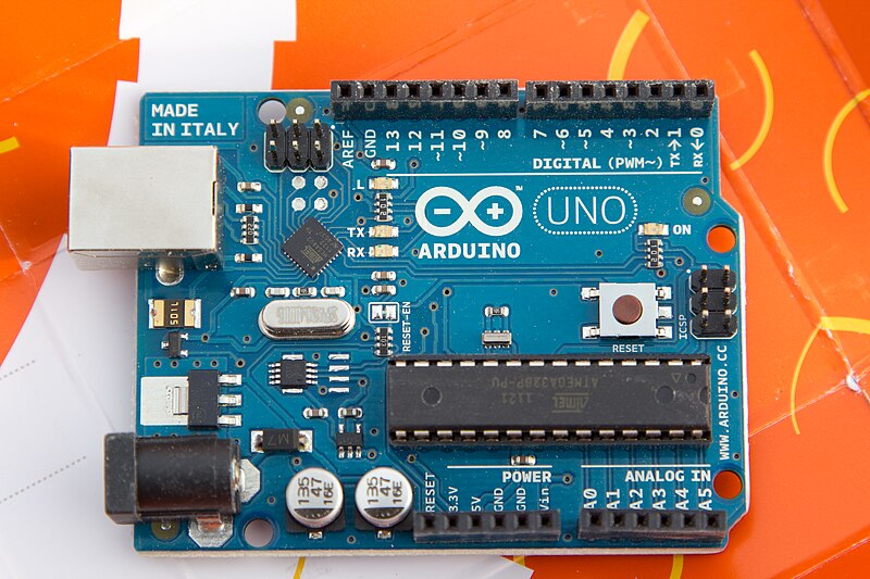
The Arduino is a series of micro-controllers that are organized in a simple consistent design. There are some that are smaller than the normal design, but most of the popular boards support the basic pinout. The most popular boards are the UNO, and the Mega. All the boards are programmed the same way using the Arduino Integrated Development Environment (IDE) over a USB connection.


The smaller boards like the Uno have about 16 general purpose IO pins, 6 Analog input pins, a serial port (SPI), and various power pins. The organization of these pins is consistent for most boards. The Uno, Diecimila, Duemilanove and the Leanardo are basically the same.


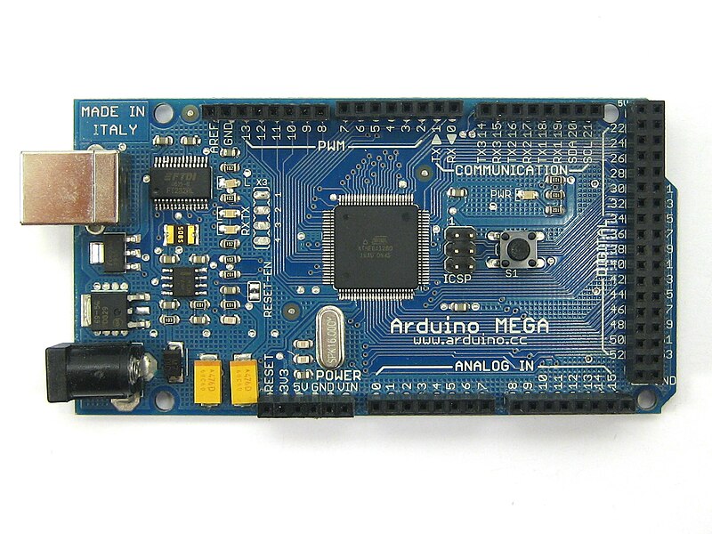
The larger boards like the Mega, have over 50 IO pins, 16 Analog input pins, the same serial interface (SPI) and power pins as the smaller boards. The layout of the board starts with the same pin organization as the smaller boards, but since the Mega board is longer the extra pins are out past the edge of the smaller boards.

Relying on this consistent pin layout has allowed expansion boards to be built. These expansion boards are known as "shields". Most of the shields add specific functionality to the basic Arduino. Shields include servo and motor controllers, GPS, ethernet, WiFi, and Bluetooth. I think there are over 100 different shields for the Arduino family of controllers as of now. 

Many of the shields allow other shields to plug into them. Having a whole stack of shields isn't uncommon. A project may include an Arduino processor board as the base, a special IO shield in the middle and either a bluetooth or WiFi shield plugged into that. The only limit to the number of shields is power available, and mechanical constraints.

Using an Arduino can be done with only the board and a USB cable. All the programming will be done using the USB cable, and power on the USB can supply the board. Most computers are limited on the amount of power supplied over the USB port, so there is a second coax power connector available to power the Arduino with more if needed for the various shields. The Arduino can run off a phone charger USB adapter once a program is loaded.

Many retail outlets are selling the Arduino processor boards and shields. Radio Shack, Micro Center and Fry's all have Arduino boards in most of their stores. Many online electronic suppliers also have Arduino boards and shields, and their selection can be more extensive. The UNO boards can be bought for as little as $10 retail. Buying a starter kit is a good idea if you have never worked extensively with electronics, since this will come with wires, LED lights, switches and various other components making connecting an Arduino to an airplane easier.  Shop around, see what you like.

The Arduino IDE is available from the Arduino web site for free. There is a version of the IDE available for most computers including: Windows, Mac, and Linux. It is an open source project, if you have another platform, you may need to get the source and compile it for your platform.

Installing the IDE is occasionally a challenge on Windows. The FTDI USB driver isn't included with Windows, so you may need to download the driver for your OS. Mac and Linux usually work without any challenges. There is plenty of help installing using the Arduino.cc forums. If you see an error, just enter that error message in the search bar for the forums, and it will probably take you to the solution.

Programming an Arduino is very simple. The IDE comes with many examples, that will run on most boards. The programs written for the Arduino in the IDE are called "sketches". The simplest example sketch is a blinking light. The blinking light sketch will blink the light on the Arduino board itself.


The sketches included are source code. To select the blink sketch, open the IDE and select File->Examples->Basics->Blink. A new window should open, showing the source code for the blink example. The text between "/*" and "*/" are comments, as is the text after "//". If you have ever worked with C or Java this syntax should be very familiar. Comments are only there for the people reading the code, the computer doesn't use that information at all.

/*
  Blink
  Turns on an LED on for one second, then off for one second, repeatedly.
 
  This example code is in the public domain.
 */
 
// Pin 13 has an LED connected on most Arduino boards.
// give it a name:
int led = 13;

// the setup routine runs once when you press reset:
void setup() {                
  // initialize the digital pin as an output.
  pinMode(led, OUTPUT);     
}

// the loop routine runs over and over again forever:
void loop() {
  digitalWrite(led, HIGH);   // turn the LED on (HIGH is the voltage level)
  delay(1000);               // wait for a second
  digitalWrite(led, LOW);    // turn the LED off by making the voltage LOW
  delay(1000);               // wait for a second
}


There are two kinds of syntax after the inital comments, function definitions and variable declarations. The line:

   int led = 13;

is a variable declaration, saying some name "led" is declared as 13, at least for now. It is at the top of the program making it a global variable. Global variables can be used anywhere in the program. In this case, when the word "led" shows up, the value 13 will replace it.

The two lines:
  void setup()
  void loop()


are function definitions. Arduino will call these two functions in every program. The setup() function is used at the begining of a program to make sure the board is set the way you want. The loop function is called the rest of the program run time, and does all the real work.

For the blink program, the setup() function is used to set the IO pin "led" (13) to be output using the pinMode() function call. Output means the computer will send messages to that pin. Input would be used for reading messages from that pin.

For the blink program, the loop() function is what does the actual blinking. digitalWrite() is a function that is part of the standard library, allowing data to be set on specific output pins. The first thing done is to digital write to the "led" (13) pin to be high, or to send 5V on that pin. delay() another function in the standard library that tells the computer to wait here for some milliseconds, in this case 1000 milliseconds, or one second. The next digital write will set the "led" (13) pin to be 0 volts or off and then the computer will delay another second and exit the loop function. The built in Arduino manager will call the loop function as soon as this loop function finishes. Each of the lines has a "//" followed by an explaination comment as to what that line does, and it helps the people reading the source code, but is only optional.

To send this program to your Arduino, the IDE will need to be set up.  Under Tools select Board and the board you are trying to program. If you have an Uno, select Tools->Board->Arduino UNO from the boards menu. Then you need to set the port. The port will be the place the board is connected to as your computer sees it. For Windows it may be COM6 or something other than COM1 or COM2. For Linux, it will probably be /dev/ttyUSB2 or something, use dmesg to see what the computer named the port when the board was plugged in. The Adruino web site has all the information in the getting started page.

Once the board and the port are set, the sketch can be uploaded to the board.  Press the forward arrow button or File->Upload or ctrl+U, to upload the code to the Arduino. At the bottom of the IDE window, the current status will be displayed. First the source code will need to be converted to AVR binary code through the process of compilation, then the resulting binary code will be sent through the serial port to the Arduino board, and the process will start running.

If everything has gone well, the LED light on the board will start blinking one second on, one second off. The code is "burned" in to the computers memory. When the Arduino is unplugged, the code is still there, but the processor will stop running. Plugging the Arduino back in, the blinking will start automatically.

To change the pattern of the blink, in the IDE, change some of the values. To make the light appear to flash, change the delay() value after the on digitalWrite() call. A very quick on, could be something like a tenth of a second (100ms). Delete one of the zeros, and upload your code. Notice how the light just blinks briefly, and stays off for the full second still. Other settings can be used to give other patterns.

I am going to end this article now. I think there is a lot to chew on, and hopefully I have wet your appetite to try new things related to controlling things using a microcontroller. Next time I will add inputs and additional outputs, including motors, switches and lights.

What else do you want to know?


Friday, June 27, 2014

Data Comm Tools We Need

I spent the last week on a business trip, and managed to go most of the week without WiFi. The airplane I flew on didn't have WiFi, and while in the car I didn't have it either. I was staying at a 5 star hotel for 4 nights, and had only marginal coverage, at $13 a night. I ended up using my mobile hot spot on my phone and burned through over half my monthly allotment LTE internet in 4 days. I learned how much I rely on data connections.


Several years ago, probably 1998 or so, my wife and I were at Oshkosh, and walked by the Iridium booth. The Iridium sales person offered us a free phone call to see how great their products are, and maybe we could use them in our airplane. This was before my wife or I had a cell phone, and we wanted to check in on the kids. After three or 4 failures, we never got to talk to the kids, and we walked away unimpressed.

About a week ago, the Airplane Geeks had the president of Iridium on the show and allowed him to hawk his products.He presented a new product that sounds like something pilots can use in the plane, and maybe other times as well. The Iridium Go looks to be the perfect implementation of the Iridium network for us.

The Iridium Go is a WiFi hotspot that will work anywhere in the world, at almost any altitude. This is the opportunity to make a tablet and phone work anywhere all the time. When in the air, the tablet can get all the data updates desired, along with making VOIP phone calls on the phone. The Go also has tracking and other useful features built in.

I know FIS-B and TIS-B should have much of the datalink covered, there are some things it won't have covered. Items like downloading whole graphical charts while in the air, or additional weather information will not be available over FIS-B.  TIS-B and FIS-B aren't available outside the CONUS either, operations there will benefit from additional datalinks.

Airlines have the ability to use Iridium datalink today, and the ICAO flight plan has a capability letter reserved for CPDLC using Iridium (J7 CPDLC FANS 1/A SATCOM (Iridium)) in Item 10. To put Iridium radios in commercial aircraft is a very expensive aftermarket event. Using the Iridium Go for non-safety of flight purposes is a much smaller cost (More than an order of magnitude!).

The price is around $600 for the GO, and while that sounds high, consider the cost of a typical smart phone is in a similar ballpark (off contract). One might guess if these devices become quite popular, the price may come down.

For tooling around in your Taylorcraft, this might be overkill, but I could see it becoming almost an expected item on a Citation, or King Air. People rely on data communications a bit more in the 21st century.

(Iridium hasn't talked to me at all, I saw this and thought this is  great product!)


Friday, June 6, 2014

Stuff To Learn

I knew the different Arduino boards are all a little different, but I didn't realize the Arduino Mega 256 was really different. My other Arduino Mega is only a 128. The Mega 128 and most of the other Arduino boards use the FTDI USB interface. The Mega 256 uses a ATMega8U2 chip, like the UNO. The boards sure look the same


Now I am using Linux to do development, so the serial port ends up being called /dev/ttyACM0 instead of some /dev/ttyUSB0. No big deal really, it is just I was surprised there were more differences than I expected. The Arduino on Linux page has many helps to get things working.

I took the basic sketch, blink and modified the loop to be sure I knew it was my code running on it.

// the loop routine runs over and over again forever:
void loop() {
  digitalWrite(led, HIGH);   // turn the LED on (HIGH is the voltage level)
  delay(100);               // wait for a tenth of a second
  digitalWrite(led, LOW);    // turn the LED off by making the voltage LOW
  delay(100);               // wait for a tenth of a second
  digitalWrite(led, HIGH);   // turn the LED on (HIGH is the voltage level)
  delay(100);               // wait for a tenth of a second
  digitalWrite(led, LOW);    // turn the LED off by making the voltage LOW
  delay(100);               // wait for a tenth of a second
  
  digitalWrite(led, HIGH);   // turn the LED on (HIGH is the voltage level)
  delay(1000);               // wait for a second
  digitalWrite(led, LOW);    // turn the LED off by making the voltage LOW
  delay(1000);               // wait for a second
}


Now I want to get things working with the display. I bought a LCD touch screen for this. The screen looks familiar, almost identical to the Sharp Zaurus screen. (we can talk all we want about iPhone/Android but the reality was there were smart devices running a *nix flavor waiting for a phone a long time before either were invented! Zaurus was the first one I had, the Nokia 770 was the second, wifi enabled internet connected personal mobile devices).


There is a thread on the Arduino forums about this device, including locations of the libraries. I am going to build a minimal graphics library so I can build a display of the basics before I start using the bluetooth connection to the Android. 


Monday, May 19, 2014

Doing The Annual Inspection

The weather is getting nice, and I am wanting to work on the plane again. It should be put in condition to fly, and that requires an annual condition inspection. My airplane, being an experimental, and built by me mostly, I have the ability to do my own conditional inspection and sign it off. It hasn't flown for almost 3 years, so I haven't done a complete conditional inspection for some of those years. This one is going to be thorough, I am in no hurry to actually fly.


I've got everything opened up. There are items that need repair (IE drip rail in the front that I broke while storing a box inside the plane), and other things that need a good looking at. I am changing the oil, and sent a sample off to a lab for analysis, to be sure the last couple years of dis-use hasn't done significant damage to the engine. The lab will test the oil for elevated levels of metals that may be early signs of engine damage.


I am looking at the firewall extensively for the engine monitor, and where to attach the monitoring computer.  Most of the smaller wires between the engine and the firewall are for sensors. The wires around the oil filter are oil temperature and pressure sensors. The silvery wires are EGT/CHT thermocouple wires. Under the engine are the fuel pressure wires.  There are the ammeter wires on either side of the shunt (that is a bit of old fashioned technology).

In the annual inspection, I found the ammeter light is burned out. This light is only needed for night flying, since I can see the instruments during the day. Each engine instrument has it's own light bulb, so I am 1/6th of the way through needing to replace them all. It'll be good to replace all the engine instruments with a smart box to monitor all this, as well as display current state.

I've started on the bluetooth code. That is a bigger challenge than I thought, mostly because the Android emulator doesn't support bluetooth. I need to keep my phone plugged in and use that for the tester. It isn't bad, but the phone has lots going on, so the log files scroll fast (and this is my only phone right now.

Soon the annual will be done, and hopefully about that time, I'll be ready to put my arduino in the plane, and start testing some of this. In the mean time, I've ordered another arduino, a mega 256. It seemed I ordered that the same day the arduino zero came out. Why am I messing with 8 bit micros when 32 bitters are about the same price? I don't know, comfort maybe, or maybe it is all I need, the 32bits may not get me anything. (The zero only has the same number of IO pins as an uno, so there isn't a big win yet, some day there may be a mega zero, until then, I'll keep using the mega).

Tuesday, May 13, 2014

More Engine Monitor Updates

This will be kind of a quick post, but the gist of it is, I've been busy. In between getting a new version of my other app out, and explaining the technology behind these gauges on my other blog, I haven't been watching a lot of TV or hanging out in bars.

The new gauges have options that work, and the interface and abstract implementation make these very flexible. Looking at all the gauges, they mostly have the same call, the size differences are sort of hard coded.

In the picture above, you will see round and bar gauges, mostly the same as before. The new changes are the round gauges can go in either direction, be 270 degree, or 180 degree (any sweep angle should work) There is one CircleGauge class that actually draws them all! The CircleGauge class is extended by things like the Ammeter class, or the Volts Meter class.

The gauges have options for clockwise/counter-clockwise, ticks, and various color options (I haven't been setting the color options, these are the  default values. The gauges can have a rotated start angle, and display the title and value in the center of the gauge.

The gauges all get their values from an EngineValues class, that can be set at any time. The next steps will be to put in the bluetooth reading code that will allow me to connect the Arduino to the engine and start measuring values.

What-cha think? Am I heading in the right direction?

Saturday, April 12, 2014

Engine Monitor Progress

I am gaining a bit of experience in Android development. Some things I did in that last app are helping, while I need to learn more to make this work. One thing I have clearly learned, the drawing canvas can be made into tiles. This is important, since if the app is to display both in portrait and landscape, it will be much easier to move individual gauges around than trying to use different offsets depending on orientation.

rough example


The other thing I learned, these gauges can have a million options! I may need about half that many before I am done as well. Should the round gauge turn clock wise or counter clock wise? Should the green arc be thick or thin, should the ticks be shown or not. Of course I can add all those options, and I still need to add more.

I've built the individual instruments using normal Object Oriented (OO) concepts. I could just as easily substituted the tachometer as a bar graph as a round gauge. I also have the ability to build an new type that can be a line graph or something, and only have to change the code a little. I can change the individual gauges, and probably not have to change the implementers code as well.

The OO concept allows a great deal of flexibility. Everything is abstracted away, such that the value of the fuel pressure will not really care what color the pointer is, or that the gauge is round or some other shape. Where it is placed on the screen is equally irrelevant, and allows the user to change the layout of the screen to suit their needs, and present the most important information in the most prominent position.

I am making progress, I just keep getting bogged down in implementation details, that can probably wait. Some of you are looking at this and saying, "it isn't very good". Fine, tell me what other things I should change to make it better looking. I've already considered OpenGL 3D looking instruments, and non-linear scales, red lines at limits, and many other things. The app will include audio and visual alerts depending on settings.

For now, I have all the instruments I need for my airplane on the screen. I have provisions in the code for 6 and 8 cylinder EGT/CHT values, as well as manifold pressure, and temperature. I want the screen layout to be customizable by the user, so they can pick the instruments they want, and where they are on the display.  


 Thanks for your feedback so far.


Sunday, April 6, 2014

After You Rewire it...

Yesterday I stopped by an estate sale. They had a Robosapian V2 for $10. This is a robot I've wanted for years, but they cost more than I could justify. I thought $10, why not. The remote seemed to work, and it had batteries in it, I thought for $10, I would take a chance on it.


It needs 6D cells and 4AAA batteries, so I stopped off and picked up some batteries for another $15. So now I am $25 into it, and it doesn't seem to work. My normal mode after buying something like this, and finding it doesn't work, is I Google for similiar failure modes. This failure mode is, it does nothing. I opened up the feet again to be sure I put the batteries in the right way, which I have, but the one pair of AAA batteries are super hot, like I can't hold them.

Reading some of the fixes suggested, was a youtube video about how easy it is to rewire this thing. I watched about half of it, and thought, this is like Tim Taylor rewiring everything just because. Another site suggested rewiring the legs. The one site suggested it is easy to open the robot up, so I thought, I can open up the torso to measure voltages on the main board.

Insulation has flaked off and is covering bits of the robot insides. 


What greeted me when I opened it up was shocking! Insulation just flaking off of the wires. Most of the wires that went to the legs had about 50% of the insulation missing. I continued opening up the robot, and when I got to the legs, there were parts where all I saw was a mass of copper, you could no longer tell one wire from another.

I thought I would try the rewiring repair. I went to Radio Shack to see what they had for wire. There was a significant gap between the 22GA wire and the 30GA wirewrap wire that they didn't have. I bought the 22GA wire to use for the motor power, and decided to cannibalize a Cat 5 cable for the logic wiring. It took about 4 hours to do all the wiring. There are several sites with details on what the wires are for.

I want to blame some MBA or manager for making a really bad choice here. I don't know for sure, but someone at the company decided to cut some corners with the quality of the wire. Some of the wire in the robot is fine, but the critical wires (the ones going from the body where the computer is, to the feet where the batteries are, and they move a lot) are just crap.

I was short of resources as well. The connectors that are in the robot are pretty cheap as well, but are a common connector. They have tin crimp on pins. Rather than risk the whole pin, or the body of the connector, I decided to strip back about an 1/8" of wire and solder my new wire on with some heat shrink to insulate the connection.

Once I got the wiring done, it still didn't work. I tried using a meter to trace the trouble. I was not getting any voltage from the AAA batteries in the one foot. When I opened that up, I found the connector in the cover was covered with corrosion, and not making good contact. After cleaning up the connection here, the robot started jiggling around and talking!


Success! I now had a working Robosapian V2. I started putting the panels back on, and covering the robot up, so it looked like it did when I brought it home. I messed up on some of the screw placement, but it went together, and looked good.

I played with the sensors for a little while last night. The blob detector is pretty good, and worked really well. The motion detector was pretty good at well, I could get it to flail backwards and scream when I swatted my hand towards the head. It walked and reached with the remote. So I went to bed.

When I got up this morning, I started messing with it more. I wasn't using the manual, just randomly pushing buttons. I clicked on the "D" button that starts the dance routine. It was playing music and moving quite a lot, then it quit. It seemed to quit on a proper down beat, but was in an odd position to end a dance.

3 of 6 wires are broken from white connector


Nothing worked again. Grrr! how much do I need to open up to find the trouble this time?  I opened the torso, and the trouble was obvious. My soldering on to the connector ends made the wire brittle. People have told me before, "don't solder your crimp connectors, it makes the wire brittle", but in this case, I didn't have much choice. Most of the wire was already missing the insulation, and I didn't think making long pigtails with lots of heat shrink was a good idea. (I didn't think of long heat shrink coated wires at all).

I've ordered some new connectors. I will replace all 4 of the connectors I soldered to like that, and make sure there is enough jiggle room between the connector and the solder joint.

After you rewire it, you do some pretty cool things with this robot!

These robots are a challenge.

Friday, April 4, 2014

App In the Playstore

Like I said in the last post, my app is in the Google PlayStore, and can be downloaded by anyone. There were some things I found out the hard way, but overall, it was a pleasant experience. Yes, I am working on the engine monitor, I just needed to get this wrapped up. I am guessing there will be updates when people start giving me feedback, and there are a couple items I want to update for the next revision.


To get an app in the store, you need to sign up as a developer.  This is a simple task, agreeing to Google's terms, and paying $25. The $25 is a one time fee, and allows you to put in as many apps as you want.

The Playstore is trying to be fair to everyone, without putting them at risk. They don't want apps that are all spam, or extortion type apps, where you can't use the app without paying something extra. They kind of control that by mostly forcing you to use their services to pay for the in app purchases, if there are any, or to clearly label your app as pay to use.

If you want to distribute your app outside the US, you need to certify that the app doesn't break any ITAR rules. They ask you to check a box, and aren't really into looking for specific certifications. That check box probably keeps Google an arms reach out of any ITAR enforcement action.

The one thing that took the most time, Google was a little more picky about my package name. This, being my first app, I went with the defaults in Android Developer Studio. When I created the app, it asked for the package name, and filled the box in with "com.example". I didn't make any plans at the time, so I left that alone.  When I uploaded the app to the playstore the first time it rejected it, saying that "com.example is reserved for special items".

You can look, according to IANA.org, example.com is available to be used for illistrative purposes:

As described in RFC 2606, a number of domains such as example.com and example.org for documentation purposes. These domains may be used as illustrative examples in documents without prior coordination with us. They are not available for registration or transfer.

Wow, who knew. For the engine monitor code, I changed that already to com.engmon, at least for now.

All the icons I had already done. If you look at the icons on a phone, they are a little better looking than in the play store. Maybe if I was making money from this app, I would hire a graphic designer to come up with something clever, but these kind of illustrate the walking outside the app requires.

I did need a large icon to get it in the play store. I didn't start with the big one(512x512 pixels) while building the app. I started with the second big one (144x144pixels), and built proper layers using gimp to build the icon. I scaled the 144 pixel image down to make the smaller icons, and that worked well, as I expected. I tried a couple trees in front of the Android, but it didn't look well. For the big image, gimp did an OK job scaling up the 144 pixel image.

The other thing the app needed, was to be built without any debugging turned on. I get it, many of the debugging facilities are entered using various networking ports. Once someone has access to an app, in a nefarious way, they can do bad stuff, due to the fact that there is really only one user for all the apps on the smart phones out there. All apps have the same permissions for everything.

Google has some funny algorithm that determines where the app shows up when you search. When I type in Acreage calculator, it find an app called Acreage Calculator (the play store allows apps to have the same name, I am guessing trademark registration would trump any conflicts, but I am not gonna worry about it). The other app converts square meters entered in a text field to acres, as a converter would do. My app didn't show up this morning. It may when it gets enough downloads, but how do you get downloads if it isn't visible?


You should down load my app and give it a shot. Please give me feedback in the Playstore, or here. Your ideas may be incorporated in the next release of the app.

Thanks for listening.


Sunday, March 30, 2014

Getting Back at It

I've finished my other Android app. It is non- aviation related, and it doesn't use an Arduino, but it proves my skill as an Android developer (or not). It may be in the Playstore real soon now. The weather is warming, and I can get at the plane in the hangar, so I am going at least make an effort to move forward with the engine monitor project.


I've been playing with the Android PFD that I really like. The  A-EFIS is really nice, and I can see this as the primary display I use going forward. Long term, before I would fly any tablet in IFR conditions, I would like a AHRS system bolted to the aircraft, and connected to the tablet. This app is good enough for daily use otherwise using only the tablet gyros. I tested this while flying on a commercial flight (I wouldn't want to test and document while flying solo in GA). 

It is time to replace the engine instruments with an Android app. I have the skills, and proved that I can get the data, I just need to put it all together. So I will document my design with this post, and move on to actually finishing it, showing my test results. I look forward to your feedback, and want to know your thoughts.

I am trying to use best practices, so I will try to use modern technology, and communications. It will still use the Arduino, since that platform is reliable and well documented.

Using the 3 layer design Model, View Controller (MVC) pattern, I will use the Arduino output as the Model, the Android display as the View and the logic to monitor and log the data as the controller. There may be redundant logging on both the Arduino and the Android. The Arduino will be attached to the aircraft, and have the aircraft data. The Android will be removable, and allow interpretation and modeling at remote locations.

The Arduino will read all the raw values from the sensors, and convert those values to actual real numbers. The actual message will contain units, so the numbers have a context.

The output from the Arduino will be in JSON format, allowing different platforms to use the information.  Someday someone may want to replace the Android display with another platform, and that will be possible using this design. The message will be sent from the Arduino about once a second, but can come more often.  A sample message will be similar to:

{"engineParams":
     ["CHTS":[
        "Cyl1": "340F", "Cyl2": "341F", "Cyl3":"348F", "Cyl4":"333F" ],
      "EGTS":[
        "Cyl1":"1530F", "Cyl2":"1520F", "Cyl3":"1550F", "Cyl4":"1545F" ],
      "RPM": 2330,
      "OilPress": "50lb",
      "OilTemp": "220F",
      "FuelPress":"25lb",
      "Volts" : 14.2,
      "Amps" : +12.3,
      "ManifoldPress", "32.29InHg",

      "Timestamp", "2142325533.5sec"]}


The Android will use this information to display graphically the current engine situation. The Android will be able to interpret these values and display the data in other units, set monitoring points with alarms, and other alerting mechanisms. Logging will try to be as similar to the Insight engine monitoring data formats (CSV), allowing existing analysis tools to utilize this data, and make common sense results.

Some of the alerts will include:
  • Low oil pressure
  • High CHT
  • High oil temprature
  • Low voltage
  • Low charge (amps)
As well as others can be programmed in.  Blinking displays and audible alerts are possible, and a combination will be used. The audio output from the Android device can be routed to most audio panels. The Android device may allow playing music, podcasts  and other entertainment functions along with the alerting functions.

Using the JSON input format can allow debugging and testing on a desktop computer. Creating or using recorded data can allow playback to the Android device. The Android emulator included with the ADK is very good, and allows devices of all types to be used, to insure the display will work. I can start working on the Android code without having a functioning Arduino device working.

I welcome your input